
User manual
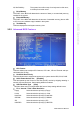
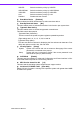
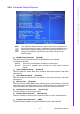
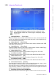
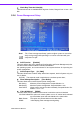
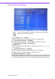
Table Of Contents
- ARK-3399
- 1 General Introduction
- 2 H/W installation
- 2.1 Introduction
- 2.2 Jumpers
- 2.3 Connectors
- Figure 2.2 ARK-3389 IO connectors drawing
- 2.3.1 ARK-3399 external I/O connectors
- 2.3.1.1 COM Connectors
- 2.3.1.2 Ethernet Connector (LAN)
- 2.3.1.3 PS2 Keyboard/Mouse Connector
- 2.3.1.4 VGA Connector
- 2.3.1.5 USB Connector
- 2.3.1.6 Power Input Connector
- 2.3.1.7 Power ON/OFF Button
- 2.3.1.8 LED Indicators
- 2.3.1.9 Audio Connector
- 2.3.1.10 DIO Connector
- 2.3.1.11 LVDS Connector
- 2.3.1.12 LCD Backlight On/Off control Connector
- 2.4 Installation
- 3 BIOS Operation
- 3.1 BIOS Introduction
- 3.2 BIOS Setup
- 3.2.1 Main Menu
- 3.2.2 Standard CMOS Features
- 3.2.3 Advanced BIOS Features
- 3.2.4 Advanced Chipset Features
- 3.2.5 Integrated Peripherals
- 3.2.6 Power Management Setup
- 3.2.7 PnP/PCI Configurations
- 3.2.8 PC Health Status
- 3.2.9 Frequency/Voltage Control
- 3.2.10 Load Optimized Defaults
- 3.2.11 Set Password
- 3.2.12 Save & Exit Setup
- 3.2.13 Quit Without Saving
- 4 Full Disassembly Procedure
- 4.1 Introduction
- Figure 4.1 Unscrew the bottom screws
- Figure 4.2 Unscrew the frame screws and remove the frame
- Figure 4.3 Unscrew the panel screws
- Figure 4.4 Unscrew the hex-bolts on the panel
- Figure 4.5 Unscrew the ground wire of LVDS cable and disconnect all the cables and boards
- Figure 4.6 Unscrew the boards’ screws and hex-bolts for disassembly
- Figure 4.7 Unscrew the power module screws on the bottom to disassemble the power module
- 4.1 Introduction
25 ARK-3399 User Manual
Chapter 3 BIOS Operation
All, But Disk/Key The system boot will not stop for a keyboard or disk error;
it will stop for al other errors.
Base Memory
The POST of the BIOS will determine the amount of base (or conventional) memory
installed in the system.
Extended Memory
The POST of the BIOS will determine the amount of extended memory (above 1MB
in CPU’s memory address map) installed in the system.
Total Memory
This item displays the total system memory size.
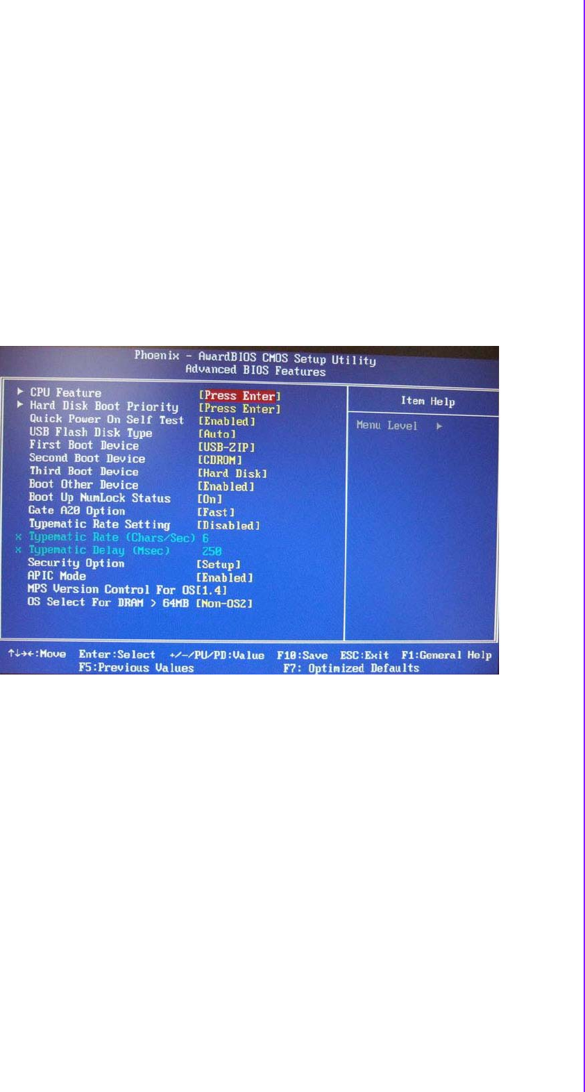
3.2.3 Advanced BIOS Features
CPU Feature
This item allows user to adjust CPU features, CPU ratio, VID and Thermal and spe-
cial feature like XD flag.
Hard Disk Boot Priority
This item allows user to select boot sequence for system device HDD, SCSI, RAID.
Quick Power On Self Test [Enabled]
This field speeds up the Power-On Self Test (POST) routine by skipping retesting a
second, third and forth time. Setup setting default is enabled.
USB Flash Disk Type [Auto]
This item allows user to changed flash disk format. Setup setting default is auto.
First / Second / Third / Other Boot Drive
Floppy Select boot device priority by Floppy.
LS120 Select boot device priority by LS120.
Hard Disk Select boot device priority by Hard Disk.
CDROM Select boot device priority by CDROM.
ZIP Select boot device priority by ZIP.
USB-FDD Select boot device priority by USB-FDD.