
User manual
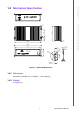
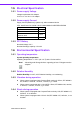
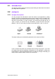
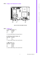
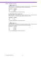
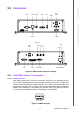
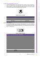
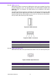
Table Of Contents
- ARK-3399
- 1 General Introduction
- 2 H/W installation
- 2.1 Introduction
- 2.2 Jumpers
- 2.3 Connectors
- Figure 2.2 ARK-3389 IO connectors drawing
- 2.3.1 ARK-3399 external I/O connectors
- 2.3.1.1 COM Connectors
- 2.3.1.2 Ethernet Connector (LAN)
- 2.3.1.3 PS2 Keyboard/Mouse Connector
- 2.3.1.4 VGA Connector
- 2.3.1.5 USB Connector
- 2.3.1.6 Power Input Connector
- 2.3.1.7 Power ON/OFF Button
- 2.3.1.8 LED Indicators
- 2.3.1.9 Audio Connector
- 2.3.1.10 DIO Connector
- 2.3.1.11 LVDS Connector
- 2.3.1.12 LCD Backlight On/Off control Connector
- 2.4 Installation
- 3 BIOS Operation
- 3.1 BIOS Introduction
- 3.2 BIOS Setup
- 3.2.1 Main Menu
- 3.2.2 Standard CMOS Features
- 3.2.3 Advanced BIOS Features
- 3.2.4 Advanced Chipset Features
- 3.2.5 Integrated Peripherals
- 3.2.6 Power Management Setup
- 3.2.7 PnP/PCI Configurations
- 3.2.8 PC Health Status
- 3.2.9 Frequency/Voltage Control
- 3.2.10 Load Optimized Defaults
- 3.2.11 Set Password
- 3.2.12 Save & Exit Setup
- 3.2.13 Quit Without Saving
- 4 Full Disassembly Procedure
- 4.1 Introduction
- Figure 4.1 Unscrew the bottom screws
- Figure 4.2 Unscrew the frame screws and remove the frame
- Figure 4.3 Unscrew the panel screws
- Figure 4.4 Unscrew the hex-bolts on the panel
- Figure 4.5 Unscrew the ground wire of LVDS cable and disconnect all the cables and boards
- Figure 4.6 Unscrew the boards’ screws and hex-bolts for disassembly
- Figure 4.7 Unscrew the power module screws on the bottom to disassemble the power module
- 4.1 Introduction
ARK-3399 User Manual 14
2.3.1.5 USB Connector
ARK-3399 provides 5 connectors of USB interface, which give complete Plug & Play
and hot swapping for up to 127 external devices. The USB interface complies with
USB UHCI, Rev. 2.0 compliant. The USB interface can be disabled in the system
BIOS setup.
The USB connectors are used for connecting any device that conforms to the USB
interface. Many recent digital devices conform to this standard. The USB interface
supports Plug and Play, which enables you to connect or disconnect a device when-
ever you want, without turning off the computer.
Figure 2.7 USB0 connector
Figure 2.8 USB1~4 connector
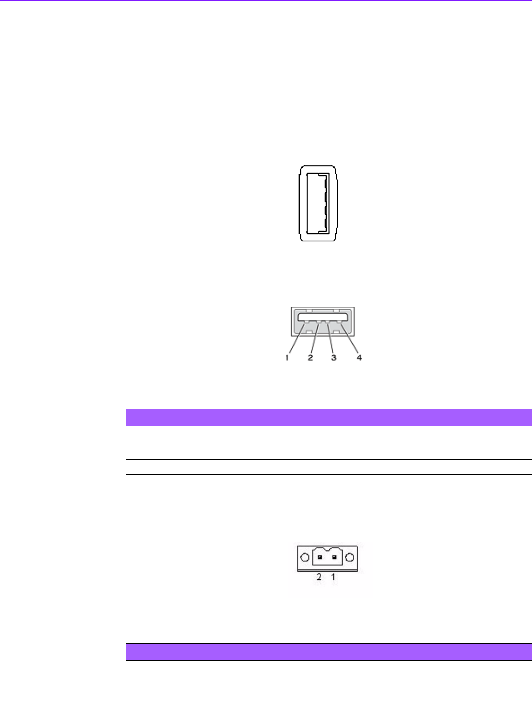
2.3.1.6 Power Input Connector
ARK-3399 comes with a two pins header that carries 9~34 V
DC
external power input.
Figure 2.9 Power Input Connector
Table 2.5: USB Connector
Pin Signal name Pin Signal name
1 VCC 2 USB_data-
3 USB_data+ 4 GND
4
3
2
1
4
3
2
1
Table 2.6: Power connector pin assignments
Pin Signal Name
1 +9~34 V
DC
2 GND