
User manual
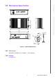
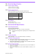
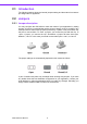
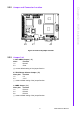
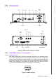
Table Of Contents
- ARK-3399
- 1 General Introduction
- 2 H/W installation
- 2.1 Introduction
- 2.2 Jumpers
- 2.3 Connectors
- Figure 2.2 ARK-3389 IO connectors drawing
- 2.3.1 ARK-3399 external I/O connectors
- 2.3.1.1 COM Connectors
- 2.3.1.2 Ethernet Connector (LAN)
- 2.3.1.3 PS2 Keyboard/Mouse Connector
- 2.3.1.4 VGA Connector
- 2.3.1.5 USB Connector
- 2.3.1.6 Power Input Connector
- 2.3.1.7 Power ON/OFF Button
- 2.3.1.8 LED Indicators
- 2.3.1.9 Audio Connector
- 2.3.1.10 DIO Connector
- 2.3.1.11 LVDS Connector
- 2.3.1.12 LCD Backlight On/Off control Connector
- 2.4 Installation
- 3 BIOS Operation
- 3.1 BIOS Introduction
- 3.2 BIOS Setup
- 3.2.1 Main Menu
- 3.2.2 Standard CMOS Features
- 3.2.3 Advanced BIOS Features
- 3.2.4 Advanced Chipset Features
- 3.2.5 Integrated Peripherals
- 3.2.6 Power Management Setup
- 3.2.7 PnP/PCI Configurations
- 3.2.8 PC Health Status
- 3.2.9 Frequency/Voltage Control
- 3.2.10 Load Optimized Defaults
- 3.2.11 Set Password
- 3.2.12 Save & Exit Setup
- 3.2.13 Quit Without Saving
- 4 Full Disassembly Procedure
- 4.1 Introduction
- Figure 4.1 Unscrew the bottom screws
- Figure 4.2 Unscrew the frame screws and remove the frame
- Figure 4.3 Unscrew the panel screws
- Figure 4.4 Unscrew the hex-bolts on the panel
- Figure 4.5 Unscrew the ground wire of LVDS cable and disconnect all the cables and boards
- Figure 4.6 Unscrew the boards’ screws and hex-bolts for disassembly
- Figure 4.7 Unscrew the power module screws on the bottom to disassemble the power module
- 4.1 Introduction
13 ARK-3399 User Manual
Chapter 2 H/W installation
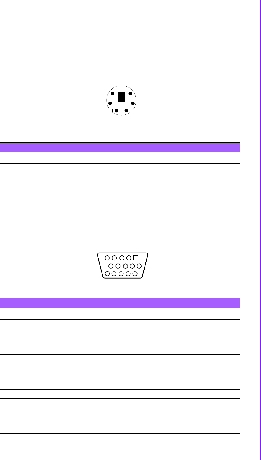
2.3.1.3 PS2 Keyboard/Mouse Connector
The ARK-3399 provides a PS/2 keyboard/mouse connector. A 6-pin mini-DIN con-
nector is located on the rear metal face plate of the ARK3399. The ARK-3399 comes
with an adapter to convert from the 6-pin mini-DIN connector to two 6-pin mini-DIN
connectors for PS/2 keyboard and PS/2 mouse connection.
Figure 2.5 PS/2 connector
2.3.1.4 VGA Connector
The ARK-3399 provides a high resolution VGA interface by a D-sub 15pin connector
to support a VGA CRT monitor. It supports VGA and VESA, up to 1920 x 1200 @ 60
Hz resolution and up to 224 MB shared memory. Pin assignments for the VGA dis-
play are detailed below.
Figure 2.6 VGA connector
Table 2.3: PS/2 Connector
Pin Signal name Pin Signal name
1 PS2_KBDAT 2 PS2_MSDAT
3GND 4VCC
5 PS2_KBCLK 6 PS2_MSCLK
5
3
12
4
6
Table 2.4: VGA Connector pin assignments
Pin Signal Name
1RED
2GREEN
3BLUE
4NC
5GND
6GND
7GND
8GND
9NC
10 GND
11 NC
12 DDC DAT
13 H-SYNC
14 V-SYNC
15 DDC CLK
5
15
1
11
10 6