
User manual
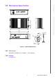
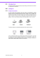
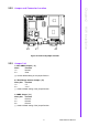
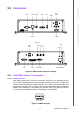
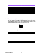
Table Of Contents
- ARK-3399
- 1 General Introduction
- 2 H/W installation
- 2.1 Introduction
- 2.2 Jumpers
- 2.3 Connectors
- Figure 2.2 ARK-3389 IO connectors drawing
- 2.3.1 ARK-3399 external I/O connectors
- 2.3.1.1 COM Connectors
- 2.3.1.2 Ethernet Connector (LAN)
- 2.3.1.3 PS2 Keyboard/Mouse Connector
- 2.3.1.4 VGA Connector
- 2.3.1.5 USB Connector
- 2.3.1.6 Power Input Connector
- 2.3.1.7 Power ON/OFF Button
- 2.3.1.8 LED Indicators
- 2.3.1.9 Audio Connector
- 2.3.1.10 DIO Connector
- 2.3.1.11 LVDS Connector
- 2.3.1.12 LCD Backlight On/Off control Connector
- 2.4 Installation
- 3 BIOS Operation
- 3.1 BIOS Introduction
- 3.2 BIOS Setup
- 3.2.1 Main Menu
- 3.2.2 Standard CMOS Features
- 3.2.3 Advanced BIOS Features
- 3.2.4 Advanced Chipset Features
- 3.2.5 Integrated Peripherals
- 3.2.6 Power Management Setup
- 3.2.7 PnP/PCI Configurations
- 3.2.8 PC Health Status
- 3.2.9 Frequency/Voltage Control
- 3.2.10 Load Optimized Defaults
- 3.2.11 Set Password
- 3.2.12 Save & Exit Setup
- 3.2.13 Quit Without Saving
- 4 Full Disassembly Procedure
- 4.1 Introduction
- Figure 4.1 Unscrew the bottom screws
- Figure 4.2 Unscrew the frame screws and remove the frame
- Figure 4.3 Unscrew the panel screws
- Figure 4.4 Unscrew the hex-bolts on the panel
- Figure 4.5 Unscrew the ground wire of LVDS cable and disconnect all the cables and boards
- Figure 4.6 Unscrew the boards’ screws and hex-bolts for disassembly
- Figure 4.7 Unscrew the power module screws on the bottom to disassemble the power module
- 4.1 Introduction
ARK-3399 User Manual 12
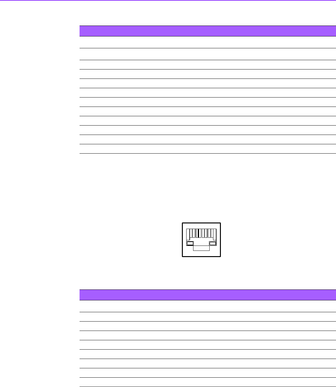
2.3.1.2 Ethernet Connector (LAN)
ARK-3399 is equipped with an Intel 82541PI Ethernet controller that is fully compliant
with IEEE 802.3u 10/100/1000Base-T CSMA/CD standards. The Ethernet port pro-
vides a standard RJ-45 jack connector with LED indicators on the front side to show
its Active/Link status (Green LED) and Speed status (Yellow LED).
Figure 2.4 Ethernet connector
Press the "Reset" button to activate the reset function.
Table 2.1: COM standard serial port pin assignments
RS-232 RS-422 RS-485
Pin Signal Name Signal Name Signal Name
1DCD Tx- DATA-
2RxD Tx+ DATA+
3 TxD Rx+ NC
4DTR Rx- NC
5 GND GND GND
6 DSR NC NC
7 RTS NC NC
8 CTS NC NC
9RI NC NC
NC represents “No Connection”
Table 2.2: RJ-45 Connector pin assignments
Pin 10/100/1000BaseT Signal Name
1TX+
2TX-
3RX+
4MDI2+
5MDI2-
6RX-
7MDI3+
8MDI3-
1818