
User manual
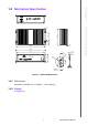
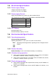
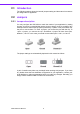
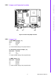
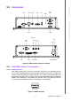
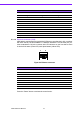
Table Of Contents
- ARK-3399
- 1 General Introduction
- 2 H/W installation
- 2.1 Introduction
- 2.2 Jumpers
- 2.3 Connectors
- Figure 2.2 ARK-3389 IO connectors drawing
- 2.3.1 ARK-3399 external I/O connectors
- 2.3.1.1 COM Connectors
- 2.3.1.2 Ethernet Connector (LAN)
- 2.3.1.3 PS2 Keyboard/Mouse Connector
- 2.3.1.4 VGA Connector
- 2.3.1.5 USB Connector
- 2.3.1.6 Power Input Connector
- 2.3.1.7 Power ON/OFF Button
- 2.3.1.8 LED Indicators
- 2.3.1.9 Audio Connector
- 2.3.1.10 DIO Connector
- 2.3.1.11 LVDS Connector
- 2.3.1.12 LCD Backlight On/Off control Connector
- 2.4 Installation
- 3 BIOS Operation
- 3.1 BIOS Introduction
- 3.2 BIOS Setup
- 3.2.1 Main Menu
- 3.2.2 Standard CMOS Features
- 3.2.3 Advanced BIOS Features
- 3.2.4 Advanced Chipset Features
- 3.2.5 Integrated Peripherals
- 3.2.6 Power Management Setup
- 3.2.7 PnP/PCI Configurations
- 3.2.8 PC Health Status
- 3.2.9 Frequency/Voltage Control
- 3.2.10 Load Optimized Defaults
- 3.2.11 Set Password
- 3.2.12 Save & Exit Setup
- 3.2.13 Quit Without Saving
- 4 Full Disassembly Procedure
- 4.1 Introduction
- Figure 4.1 Unscrew the bottom screws
- Figure 4.2 Unscrew the frame screws and remove the frame
- Figure 4.3 Unscrew the panel screws
- Figure 4.4 Unscrew the hex-bolts on the panel
- Figure 4.5 Unscrew the ground wire of LVDS cable and disconnect all the cables and boards
- Figure 4.6 Unscrew the boards’ screws and hex-bolts for disassembly
- Figure 4.7 Unscrew the power module screws on the bottom to disassemble the power module
- 4.1 Introduction
11 ARK-3399 User Manual
Chapter 2 H/W installation
2.3 Connectors
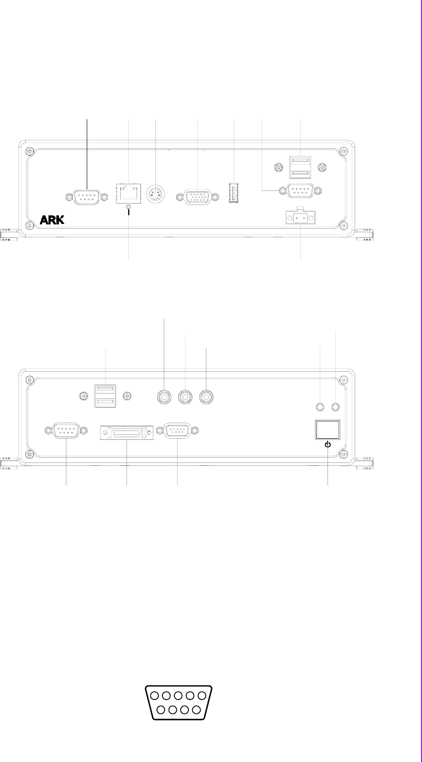
Figure 2.2 ARK-3389 IO connectors drawing
2.3.1 ARK-3399 external I/O connectors
2.3.1.1 COM Connectors
ARK-3399 provides two D-sub 9-pin connectors, which offer one standard RS-232
and one RS-232/422/485 serial communication interface ports each as COM1 and
COM2. The default setting of COM2 is RS-232, if you want to use RS-422/485, Two
things have to be done. first, you need to replace the original cable with the dedicated
RS485, P/N:1700001967, in accessory box. Second, Jumper J3 referred to section
2.2.4 need to be adjusted to either 3-4 for RS485 or 5-6 for RS422.
Figure 2.3 COM connector
LAN1
RESET
KB/MS
VGA
USB
USB1
USB2
COM2
DC INPUT
POWER ON/OFF
USB3
USB4
LINE-OUT
LINE-IN
MIC
BACKLIGHT
LVDS
DIO
PWR
HDD
3399
COM1
LAN1
RESE T
KB/MS
VGA
USB
USB2
USB1
COM2
-DCIN+
DC 9 V ~ 34V
VCCGND
PWR HDD
MICLINE-INLINE-OUT
BACKLIGHT
COM1
LVD S
DIO
USB4
USB3
15
9
6
324
78