User Manual ARK-3399 Compact Embedded Computer
Copyright The documentation and the software included with this product are copyrighted 2008 by Advantech Co., Ltd. All rights are reserved. Advantech Co., Ltd. reserves the right to make improvements in the products described in this manual at any time without notice. No part of this manual may be reproduced, copied, translated or transmitted in any form or by any means without the prior written permission of Advantech Co., Ltd. Information provided in this manual is intended to be accurate and reliable.
Product Warranty (2 years) Advantech warrants to you, the original purchaser, that each of its products will be free from defects in materials and workmanship for two years from the date of purchase. This warranty does not apply to any products which have been repaired or altered by persons other than repair personnel authorized by Advantech, or which have been subject to misuse, abuse, accident or improper installation.
Technical Support and Assistance 1. 2. Visit the Advantech web site at www.advantech.com/support where you can find the latest information about the product. Contact your distributor, sales representative, or Advantech's customer service center for technical support if you need additional assistance.
Contents Chapter 1 General Introduction ...........................1 1.1 1.2 1.3 Introduction ............................................................................................... 2 Product Feature ........................................................................................ 2 Chipset ...................................................................................................... 3 1.3.1 Functional Specification ................................................................
2.4.1 2.4.2 2.4.3 Chapter Chapter HDD Installation.......................................................................... 17 Figure 2.13Unscrew the HDD door screws ................................ 17 Figure 2.14Assemble HDD and HDD frame by 4 Screws .......... 18 Figure 2.15Screw on the HDD damper screws to assemble the HDD door and HDD frame ....................................... 18 Figure 2.16Connect the HDD cables.......................................... 19 Memory Installation...................
Chapter 1 1 General Introduction This chapter gives background information on ARK-3399 series.
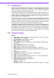
1.1 Introduction ARK-3399 Fanless Embedded Box Computer is an ideal application ready system platform solution. All electronics are protected in a compact sealed aluminum case for easy embedding in customers own housing, or as a stand-alone application, where space is limited and the environment harsh. A solid sealed aluminum case provides vibration and dust resistance while also providing a passive cooling solution.
1.3.1 Functional Specification 1.3.1.1 Processor Processor CPU supports. Support 533/667 MHz Source-Synchronous Processor System Bus. Support Intel® Core Duo LV L2400 at 1.66 GHz / Intel® Core2 Duo ULV U7500 at 1.06 GHz / Intel® Celeron-M ULV 423 at 1.06 GHz 35mm * 35mm Micro-FCBGA Package. 1.3.1.
Audio Link SB: Intel® NH82801GBM chip supports. Supports HD Codec Supports Link for Audio and Telephony CODECS Ear Phone Jack USB Interface SB: Intel® NH82801GBM chip supports. USB host interface with support for 5 USB 2.0 ports All ports are High-Speed, Full-Speed, and Low-Speed capable Supports legacy keyboard/mouse software USB connecter on board: USB conn 4P 180D(M) DIP x 1 USB dual connecter on board: USB conn 8P 90D(M) DIP x 2 Power Management SB: Intel® NH82801GBM chip supports.
Chapter 1 1.4 Mechanical Specification 137.25 72.5 26.3 3.5 252.5 264.50 240 (3.5) B R4 1.5 R2.5 6 69.20 R2 Section B-B Detailed "A" SCALE 4 :1 B Figure 1.1 ARK-3399 Dimensions 1.4.1 Dimension 264.5[10.41] x 69.2[2.72] x 137.25[5.4] Unit: mm[Inch] 1.4.2 Weight 2.0 kg (4.
1.5 Electrical Specification 1.5.1 Power supply Voltage Voltage requirement with Adaptor: 9 VDC-8 A ~ 34 VDC-2.2 A Adaptor 1.5.2 Power supply Current Supply Current (Maximum), system only, without external device CPU: Intel® Core Duo L2400 1.66 G, RAM:533MHz 512GB DDR2 SDRAM Adaptor 19 V BIOS 1.2 A WINXP Idle 1.25 A WINXP BURN IN TEST 1.42 A Suspend 0.7 A 1.5.3 RTC Battery Norminal Voltage: 3.0 V Nominal discharge capacity: 210 mAh 1.6 Environmental Specification 1.6.
Chapter 2 2 H/W installation This chapter explains the setup procedures of the ARK-3399 hardware.
2.1 Introduction The following sections show the internal jumpers setting and the external connectors pin assignment for application. 2.2 Jumpers 2.2.1 Jumper description You may configure the ARK-3399 to match the needs of your application by setting jumpers. A jumper is a metal bridge used to close an electric circuit. It consists of two metal pins and a small metal clip (often protected by a plastic cover) that slides over the pins to connect them. To .close.
J1 H/W installation J3 Chapter 2 2.2.2 Jumper and Connector Location J2 Figure 2.1 ARK-3399 jumper location 2.2.3 Jumper List 1. Clear CMOS Jumper ( J1 ) Close Function 1-2 Normal* 2-3 Clear (*): means default setting of the jumper/function. 2. LVDS Voltage Selector Jumper ( J2 ) Close pins Function 1-2 5V 2-3 3.3 V* (*): means default setting of the jumper/function. 3. COM2 Jumper ( J3 ) Close pins Function 1-2 RS-232* 3-4 RS-485 5-6 RS-422 (*): means default setting of the jumper/function.
2.2.4 Jumper Settings 1. CMOS Jumper ( J1 ) ARK-3399 series of embedded box computer provide a jumper - J1 located on the internal board for selecting the CMOS of Clear or Normal status. Close pins Function 1-2 Normal* 2-3 Clear (*): means default setting of the jumper/function. 2. LVDS Voltage Selector Jumper ( J2 ) ARK-3399 series of embedded box computer provide a jumper - J2 located on the internal board for selecting the LVDS Voltage to output 5V or 3.3V. Close pins Function 1-2 5V 2-3 3.
LAN 1 KB/M S CO M 1 VG A U SB CO M 2 Chapter 2 2.3 Connectors U SB1 U SB2 U SB 1 COM2 LAN1 COM1 3399 K B /M S USB V GA GND VCC - D C IN + DC 9 V ~ 3 4V R ESE T D C IN PUT R ESET LIN E-O UT H DD LIN E-IN U SB3 U SB4 M IC PWR U SB 3 L I N E -O U T U SB 4 D IO DIO L I N E -I N M IC PWR LV D S B A C K L IG H T L VDS B ACKL IG H T HD D PO W ER O N/O FF Figure 2.2 ARK-3389 IO connectors drawing 2.3.1 ARK-3399 external I/O connectors 2.3.1.
Table 2.1: COM standard serial port pin assignments RS-232 RS-422 RS-485 Pin Signal Name Signal Name Signal Name 1 DCD Tx- DATA- 2 RxD Tx+ DATA+ 3 TxD Rx+ NC 4 DTR Rx- NC 5 GND GND GND 6 DSR NC NC 7 RTS NC NC 8 CTS NC NC 9 RI NC NC NC represents “No Connection” 2.3.1.2 Ethernet Connector (LAN) ARK-3399 is equipped with an Intel 82541PI Ethernet controller that is fully compliant with IEEE 802.3u 10/100/1000Base-T CSMA/CD standards.
6 5 4 3 1 Figure 2.5 PS/2 connector Table 2.3: PS/2 Connector Pin Signal name Pin Signal name 1 PS2_KBDAT 2 PS2_MSDAT 3 GND 4 VCC 5 PS2_KBCLK 6 PS2_MSCLK 2.3.1.4 VGA Connector The ARK-3399 provides a high resolution VGA interface by a D-sub 15pin connector to support a VGA CRT monitor. It supports VGA and VESA, up to 1920 x 1200 @ 60 Hz resolution and up to 224 MB shared memory. Pin assignments for the VGA display are detailed below. 5 1 10 6 15 11 Figure 2.
2.3.1.5 USB Connector ARK-3399 provides 5 connectors of USB interface, which give complete Plug & Play and hot swapping for up to 127 external devices. The USB interface complies with USB UHCI, Rev. 2.0 compliant. The USB interface can be disabled in the system BIOS setup. The USB connectors are used for connecting any device that conforms to the USB interface. Many recent digital devices conform to this standard.
Note! Re-start Interval Time must be at least 3 seconds. 2.3.1.9 Audio Connector The ARK-3399 offers HD (High definition) Audio ports by three phone jack connectors of Speaker_Out, Mic_In and Line_In, Table 2.7: Line-In Connector Footprint Phone Jack 3.5φP, 90 Degree, Female Table 2.8: Speaker-Out Connector Footprint Phone Jack 3.5φP, 90 Degree, Female Table 2.9: Mic-In Connector Footprint Phone Jack 3.5φP, 90 Degree, Female 2.3.1.
2.3.1.11 LVDS Connector The ARK-3399 comes with a D-Sub 26-pin connector that carries LVDS signal output, and can direct connect to LVDS LCD Display via external cable. The system also provide a jumper of J2 on internal motherboard for selecting the LCD signal power of 5V or 3.3V, please refer to the jumper table of J2, and “Full Disassembly Procedure” to adjust it. Up. The default setting of J2 is 3.3V. Figure 2.11 LVDS Connector Table 2.
Signal name 1 +12 V 2 GND 3 BKLTEN 4 VBR 5 +5 V 6 LVDS_DCLK 7 LVDS_DDAT 8 Reserved 9 Reserved H/W installation Pin 2.4 Installation 2.4.1 HDD Installation 1. Chapter 2 Table 2.12: LCD Backlight Connector Pin Assignment Unscrew the HDD door screws. Figure 2.
2. Assemble HDD and HDD frame by 4 Screws. Figure 2.14 Assemble HDD and HDD frame by 4 Screws 3. Screw on the HDD damper screws to assemble the HDD door and HDD frame. Figure 2.
Connect the HDD cables. Chapter 2 4. H/W installation Figure 2.16 Connect the HDD cables 5. Reverse the 2.4.1-1 to cover back the HDD door. 2.4.2 Memory Installation 1. 2. Refer 2.4.1-1 to open the HDD door. Install the memory module into the SO-DIMM socket at the bottom of the Main board. Figure 2.17 Install the memory module into the SO-DIMM socket at the bottom of the Main board 3. Reverse the 2.4.1-1 to cover back the HDD door.
2.4.3 CF card Installation 1. 2. Refer 2.4.1-1 to open the HDD door. Install the CF card into the CF slot at the bottom of the Main board. Figure 2.18 Install the CF card into the CF slot at the bottom of the Main board 3. Reverse the 2.4.1-1 to cover back the HDD door.
Chapter 3 3 BIOS Operation This chapter describes how to set BIOS configuration data.
3.1 BIOS Introduction Advantech provide full-featured AwardBIOS 6.0 and delivers the superior performance, compatibility and functionality that manufactures of Industry PC and Embedded boards, itís many options and extensions let you customize your products to a wide range of designs and target markets. The modular, adaptable AwardBIOS 6.
Press to enter AwardBIOS CMOS Setup Utility, the Main Menu will appear on the screen. Use arrow keys to select among the items and press to accept or enter the sub-menu. Chapter 3 3.2.1 Main Menu BIOS Operation Standard CMOS Features This setup page includes all the items in standard compatible BIOS. Advanced BIOS Features This setup page includes all the items of Award BIOS enhanced features.
3.2.2 Standard CMOS Features Date The date format is , , , . Week From Sun to Sat, determined and display by BIOS only Month From Jan to Dec. Day From 1 to 31 Year From 1999 through 2098 Time The times format in , base on the 24-hour time IDE Channel 0 Master IDE HDD Auto-Detection Press "Enter" for automatic device detection. SATA Channel 0/1 SATA HDD Auto-Detection Press "Enter" for automatic device detection.
The system boot will not stop for a keyboard or disk error; it will stop for al other errors. 3.2.3 Advanced BIOS Features CPU Feature This item allows user to adjust CPU features, CPU ratio, VID and Thermal and special feature like XD flag. Hard Disk Boot Priority This item allows user to select boot sequence for system device HDD, SCSI, RAID. Quick Power On Self Test [Enabled] This field speeds up the Power-On Self Test (POST) routine by skipping retesting a second, third and forth time.
USB-ZIP Select boot device priority by USB-ZIP. USB-CDROM USB-HDD Select boot device priority by USB-CDROM. Select boot device priority by USB-HDD. LAN Select boot device priority by LAN. Disabled Disable this boot function. Boot Other Device [Enabled] When enabled, the BIOS will automatic to select next boot device. Boot Up NumLock Status [On] This item enables users to activate the Number Lock function upon system boot.
Chapter 3 3.2.4 Advanced Chipset Features BIOS Operation Note! This “Advanced Chipset Features” option controls the configuration of the boardís chipset, this page is developed by Chipset independent, for control chipset register setting and fine tune system performance. It is strongly recommended only technical users make changes to the default settings. DRAM Timing Selectable [By SPD] This option refers to the method by which the DRAM timing is selected. The default is “By SPD”.
DVMT Mode [DVMT] Intel's Dynamic Video Memory Technology (DVMT) takes that concept further by allowing the system to dynamically allocate memory resources according to the demands of the system at any point in time. The key idea in DVMT is to improve the efficiency of the memory allocated to either system or graphics processor. The BIOS feature that controls all this is the DVMT Mode BIOS feature. It allows you to select the DVMT operating mode.
Chapter 3 3.2.5 Integrated Peripherals BIOS Operation Note! This “Integrated Peripherals” option controls the configuration of the boardís chipset, includes IDE, ATA, this page is developed by Chipset independent. OnChip IDE Device [Press Enter] This item enables users to set the OnChip IDE device status, includes enable IDE devices and setting PIO and DMA access mode, and some of new chipset also support for SATA device (Serial-ATA).
Watch Dog Timer-Out Value[00] This item allows user to enabled watch dog time of value, Range is from 10 sec ~ 255 Min. 3.2.6 Power Management Setup Note! This “Power management Setup” option configure system to most effectively saving energy while operating in a manner consistent with your computer use style.
ARK-3399 User Manual BIOS Operation 31 Chapter 3 Video Off in suspend [Yes] This item allows user to determine the manner is which the monitor is blanked. No Screen is off occasion when system into suspend mode. Yes Screen is never be turn off. Suspend Type [Stop Grant] This option controls processor power control in two states “PwrOn Suspend” and “Stop Grant”. User can select the state depending on your need. It is recommended to select ìPwrOn Suspendî. The default is “Stop Grant”.
3.2.7 PnP/PCI Configurations Note! This “PnP/PCI Configurations” option is setting up the IRQ and DMA (both PnP and PCI bus assignments. Init Display First [PCI Slot] This item is setting for start up Video output from PCI or Onboard device. Reset Configuration Data [Disabled] This item allow user to clear any PnP configuration data stored in the BIOS.
This “PC Health Status” option controls the Thermal, FAN and Voltage status of the board. this page is developed by Chipset independent. Shutdown Temperature [Disabled] This item enables users to set the limitation of CPU temperature, the range is from 85°C through 100°C. 3.2.9 Frequency/Voltage Control 33 ARK-3399 User Manual BIOS Operation Note! Chapter 3 3.2.
Note! This “Frequency/Voltage Control” option controls the CPU Host and PCI frequency, this page is developed by CPU and Chipset independent, some items will show up when you install a processor which supports this function. Auto Detect PCI Clk [Enabled] This item determines PCI clock detection by auto or not. Spread Spectrum [Disabled] This item enables users to set the spread spectrum modulation. 3.2.
Chapter 3 3.2.11 Set Password BIOS Operation Note! To enable this feature, you should first go to the Advanced BIOS Features menu, choose the Security Option, and select either Setup or System, depending on which aspect you want password protected. Setup requires a password only to enter Setup. System requires the password either to enter Setup or to boot the system. A password may be at most 8 characters long. To Establish Password 1.
To Disable Password 1. Choose the Set Password option from the CMOS Setup Utility main menu and press . 2. When you see “Enter Password”, enter the existing password and press . 3. You will see “Confirm Password”. Type it again, and press . 4. Select Set Password again, and at the “Enter Password” prompt, please donít enter anything; just press . 5. At the “Confirm Password” prompt, again, donít type in anything; just press . 6.
Chapter 3 3.2.13 Quit Without Saving BIOS Operation Note! Type “Y” will quit the BIOS Setup Utility without saving to CMOS. Type “N” will return to BIOS Setup Utility.
ARK-3399 User Manual 38
Chapter 4 4 Full Disassembly Procedure This chapter introduce how to disassembly the system.
4.1 Introduction If you want to completely disassemble the ARK-3399, follow the step-by-step procedures below. Users should be aware that Advantech Co., Ltd. takes no responsibility Whatsoever for any problems or damage caused by user disassembly of the ARK3399. Make sure the power cord of the ARK-3399 is unplugged before you start disassembly. 1. Unscrew the bottom screws. Figure 4.1 Unscrew the bottom screws 2. Unscrew the frame screws and remove the frame. Figure 4.
Unscrew the panel screws. Chapter 4 3. Full Disassembly Procedure Figure 4.3 Unscrew the panel screws 4. Unscrew the hex-bolts on the panel. Figure 4.4 Unscrew the hex-bolts on the panel 5. 6. Repeat the instruction 4.2~4.5 to disassemble the opposite panel. Remove the top cover.
7. Unscrew the ground wire of LVDS cable and disconnect all the cables and boards. Figure 4.5 Unscrew the ground wire of LVDS cable and disconnect all the cables and boards 8. Unscrew the boards’ screws and hex-bolts for disassembly. Figure 4.
Unscrew the power module screws on the bottom to disassemble the power module. 43 ARK-3399 User Manual Full Disassembly Procedure Figure 4.7 Unscrew the power module screws on the bottom to disassemble the power module Chapter 4 9.
www.advantech.com Please verify specifications before quoting. This guide is intended for reference purposes only. All product specifications are subject to change without notice. No part of this publication may be reproduced in any form or by any means, electronic, photocopying, recording or otherwise, without prior written permission of the publisher. All brand and product names are trademarks or registered trademarks of their respective companies. © Advantech Co., Ltd.