User Manual AIMB-766 Socket LGA 775Core 2 Quad / Intel Core 2 Duo processor / Intel Pentium Dual Core / Celeron 1333 MHz FSB Industrial ATX Motherboard with PCIe/DDR2/ Dual GbE
Copyright The documentation and the software included with this product are copyrighted 2008 by Advantech Co., Ltd. All rights are reserved. Advantech Co., Ltd. reserves the right to make improvements in the products described in this manual at any time without notice. No part of this manual may be reproduced, copied, translated or transmitted in any form or by any means without the prior written permission of Advantech Co., Ltd. Information provided in this manual is intended to be accurate and reliable.
A Message to the Customer Advantech Customer Services Each and every Advantech product is built to the most exacting specifications to ensure reliable performance in the harsh and demanding conditions typical of industrial environments. Whether your new Advantech equipment is destined for the laboratory or the factory floor, you can be assured that your product will provide the reliability and ease of operation for which the name Advantech has come to be known. Your satisfaction is our primary concern.
Declaration of Conformity FCC This device complies with the requirements in part 15 of the FCC rules: Operation is subject to the following two conditions: ! This device may not cause harmful interference ! This device must accept any interference received, including interference that may cause undesired operation. This equipment has been tested and found to comply with the limits for a Class A digital device, pursuant to Part 15 of the FCC Rules.
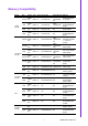
Memory Compatibility Brand Apacer (RoHS) Size Speed Type ECC Vendor PN Advantech PN Memory 512 MB DDR2 533 DDR2 N 78.91G66.420 96D2512M533NNAP ELPIDA E5108AG5C-E (64x8) 1 GB DDR2 533 DDR2 N 78.01G66.420 96D21G533NN-AP ELPIDA E5108AGBG-6E-E (64x8) 1 GB DDR2 800 DDR2 N 78.01G91.404 NA SEC 746 ZCE7 K4T51083QE 1 GB DDR2 667 DDR2 N 78.01G92.420 NA ELPIDA E5108AGBG-6E-E (64x8) infineon HYB18T512160AF3 .
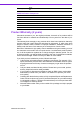
Samsung 1 GB DDR2 800 DDR2 N AIMB-766 Feature Comparison LAN/Model AIMB-766G2-00A1E AIMB-766VG-00A1E Chipset Q35+ICH9DO Q35+ICH9 SATA 6 4 SW RAID 0, 1, 5, 10 None LAN1 Intel 82556DM Intel 82556DM LAN2 Intel 82573L None AMT 3.0 Yes No Product Warranty (2 years) Advantech warrants to you, the original purchaser, that each of its products will be free from defects in materials and workmanship for two years from the date of purchase.
Initial Inspection Before you begin installing your motherboard, please make sure that the following materials have been shipped: ! AIMB-766 Intel Core 2 Quad/ Core 2 Duo/ Pentium Dual Core/ Celeron processor based industrial motherboard ! 1 AIMB-766 startup manual ! 1 Driver CD (user's manual is included) ! 1 FDD cable ! 1 Ultra ATA 66/100 HDD cable ! 2 Serial ATA HDD data cable ! 2 Serial ATA HDD power cable ! 2 COM port cable kit (2 to 2, 1 to 1) ! 1 I/O port bracket ! 1 jumper package ! 1 warranty card
AIMB-766 User Manual viii
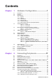
Contents Chapter 1 Hardware Configuration......................1 1.1 1.2 1.3 1.10 1.11 1.12 1.13 Introduction ............................................................................................... 2 Features .................................................................................................... 3 Specifications ............................................................................................ 4 1.3.1 System ................................................................
2.18 2.19 2.20 2.21 2.22 2.23 2.24 2.12.4 ATX Soft Power Switch (JFP1 pins 1 & 2).................................. 29 2.12.5 Reset Connector (JFP1 pins 3 & 4) ............................................ 29 Line Out, Mic In Connector (AUDIO1) .................................................... 30 8-pin Alarm Board Connector (VOLT1)................................................... 31 Case Open Connector (JCASE1) ...........................................................
3.11 3.12 Chapter Figure 3.19Password Configuration ........................................... 58 Advanced Chipset Settings ..................................................................... 59 Figure 3.20Advanced Chipset Settings ...................................... 59 Figure 3.21 North Bridge Configuration ...................................... 59 3.11.1 North Bridge Chipset Configuration ............................................ 60 Figure 3.22Video function configuration .....................
B.4 B.5 B.6 B.7 B.8 B.9 B.10 B.11 B.12 B.13 B.14 B.15 B.16 B.17 B.18 B.19 B.20 B.21 B.22 B.23 B.24 B.25 B.26 B.27 B.28 B.29 B.30 AIMB-766 User Manual Table B.3: Parallel Port (LPT1).................................................. 94 USB Header (USB56, USB78, USB910 & USB1112) ............................ 94 Table B.4: USB Header (USB56,USB78,USB910).................... 94 VGA Connector (VGA1).......................................................................... 95 Table B.5: VGA Connector (VGA1) ...
Chapter 1 Hardware Configuration 1
1.1 Introduction The AIMB-766 is the most advanced Intel Q35 product for industrial applications that require high-performance computing. The motherboard supports Intel Core 2 Duo / Core 2 Quad / Pentium Dual Core / Celeron processors with 800/1066/1333 MHz front side bus and DDR2 667/ 800 MHz memory up to 8 GB. The AIMB-766 incorporates the Intel Q35 chipset to offer cost-effective integrated graphics.
! ! ! ! ! 3 AIMB-766 User Manual Hardware Configuration ! PCIe architecture: The Intel Q35 and ICH9 DO (or ICH9) PCIe chipset supports 1 PCIe x16 slot, 2 PCIe x1 slot and a PCIe x1 link for the Gigabit LAN. High Performance I/O Capability: Dual/single Gigabit LAN via PCIe x1 bus, 4 PCI 32-bit/33MHz PCI slots, 6 SATA2 connectors and 12 USB 2.0 ports.
1.3 Specifications 1.3.1 System ! CPU: Intel LGA 775 Core 2 Quad, Core 2 Duo, Pentium Dual Core, Celeron up to 2.83/3.16/2.2/2.0 GHz, FSB 800/1066/1333 MHz. Advantech also certifies several optional high-performance CPU coolers for high-speed CPUs in 2U chassis or in high-temperature environments Note! Advantech certifies two LGA775 CPU cooler solutions.
! ! ! ! ! 1.3.4 Ethernet LAN ! ! ! Supports single/dual 10/100/1000Base-T Ethernet port(s) via PCIe x1 bus which provides a 500 MB/s data transmission rate. Interface: 10/100/1000Base-T Controller: LAN1: Intel 82766DM, LAN2: Intel 82573L 1.3.5 Industrial Features ! Watchdog timer: Can generate a system reset or NC. The watchdog timer is programmable, with each unit equal to one second or one minute (255 levels) 1.3.
1.4 Jumpers and Connectors Connectors on the AIMB-766 motherboard link it to external devices such as hard disk drives and a keyboard. In addition, the board has a number of jumpers that are used to configure your system for your application. The tables below list the function of each of the jumpers and connectors. Later sections in this chapter give instructions on setting jumpers. Chapter 2 gives instructions for connecting external devices to your motherboard. Table 1.
Chapter 1 Table 1.
1.5 Board Layout: Jumper and Connector Locations JFP3 JFP2 JFP1 JWDT1 JOBS1 Figure 1.1 Jumper and Connector Locations Figure 1.
Chapter 1 1.6 AIMB-766 Block Diagram Hardware Configuration Figure 1.
1.7 Safety Precautions Warning! Always completely disconnect the power cord from your chassis whenever you work with the hardware. Do not make connections while the power is on. Sensitive electronic components can be damaged by sudden power surges. Only experienced electronics personnel should open the PC chassis. Caution! Always ground yourself to remove any static charge before touching the motherboard. Modern electronic devices are very sensitive to static electric charges.
This section provides instructions on how to configure your motherboard by setting the jumpers. It also includes the motherboard default settings and your options for each jumper. 1.8.1 How to set jumpers 1.8.2 CMOS clear (CMOS1) The AIMB-766 motherboard contains a jumper that can erase CMOS data and reset the system BIOS information. Normally this jumper should be set with pins 1-2 closed.
1.8.3 Watchdog timer output (JWDT1) The AIMB-766 contains a watchdog timer that will reset the CPU. This feature means the AIMB-766 will recover from a software failure or an EMI problem. The JSETCOM2 jumper settings control the outcome of what the computer will do in the event the watchdog timer is tripped. Table 1.4: Watchdog timer output (JWDT1) Function Jumper Setting NC 1-2 closed * Reset 2-3 closed * default setting Note! The interrupt output of the watchdog timer is a low level signal.
The AIMB-766 has four sockets for 240-pin dual inline memory modules (DIMMs) in two memory channels. All these sockets use 1.8 V unbuffered double data rate synchronous DRAMs (DDR SDRAM). They are available in capacities of 256, 512 1024 and 2048 MB. The sockets can be filled in any combination with DIMMs of any size, giving a total memory size between 256 MB and 8 GB. The AIMB-766 can accept DDR2 SDRAM memory chips without parity. Also note that the AIMB-766 accepts DDR2 667/800 MHz SDRAM, and DDR2 SDRAM.
1.12 Processor Installation The AIMB-766 is designed for Intel Core 2 Quad, Core 2 Duo, Pentium dual-core, Celeron D processors. 1. Pull the bar besides the CPU socket outward and lift it. 2. Align the triangular marking on the processor with the cut edge of the socket.
Put back the socket cap and press down the bar to fix it. Chapter 1 3. AD PCI slot INT PCI1 PCI2 PCI3 PCI4 31 25 29 28 A B D D A B C A A B C D B B C D A C C D 15 AIMB-766 User Manual Hardware Configuration 1.
AIMB-766 User Manual 16
Chapter 2 Connecting Peripherals 2
2.1 Introduction You can access most of the connectors from the top of the board as it is being installed in the chassis. If you have a number of cards installed, you may need to partially remove a card to make all the connections. 2.2 Primary (IDE1) IDE Connector You can attach up to one IDE (Integrated Drive Electronics) drive to the AIMB-766’s built-in controller. Wire number 1 on the cable is red or blue and the other wires are gray. Connect one end to connector IDE1 on the motherboard.
Chapter 2 2.3 Floppy Drive Connector (FDD1) Connecting Peripherals You can attach up to two floppy disk drives to the AIMB-766’s onboard controller. You can use 3.5" (720 KB, 1.44 MB) drives. The motherboard comes with a 34-pin daisy-chain drive connector cable. On one end of the cable is a 34-pin flat-cable connector. On the other end are two 34-pin flatcable connectors (usually used for 3.5" drives). The connector on the end (after the twist in the cable) connects to the A: floppy drive.
2.4 Parallel Port (LPT1) The parallel port is normally used to connect the motherboard to a printer. The AIMB-766 includes an onboard parallel port, accessed through a 26-pin flatcable connector, LPT1.
LAN1_USB12 LAN2_USB34 21 USB56 USB78 USB910 USB1112 AIMB-766 User Manual Connecting Peripherals These ports support Plug & Play and hot swapping for up to 127 external devices. The USB ports comply with USB Specification Rev. 2.0. Transmission rates of up to 480 Mbps and fuse protection are supported. The USB interface can be disabled in the system BIOS setup. The AIMB-766 is equipped with one or two high-performance 1000 Mbps Ethernet LANs. They are supported by all major network operating systems.
2.6 VGA Connector (VGA1) 5 10 15 1 6 11 The AIMB-766 includes a VGA interface that can drive conventional CRT displays. VGA1 is a standard 15-pin D-SUB connector commonly used for VGA. Pin assignments for CRT connector VGA1 are detailed in Appendix B.
COM2 COM3 COM4 The AIMB-766 offers two serial ports (one on the rear panel and one onboard). JP1 is used to select the RS 232/422/485 mode for COM2. These ports can connect to a serial mouse, printer or communications network. The IRQ and address ranges for both ports are fixed. However, if you want to disable the port or change these parameters later, you can do this in the system BIOS setup. Different devices implement the RS-232/422/485 standards in different ways.
2.8 PS/2 Keyboard and Mouse Connector (KBMS1) Two 6-pin mini-DIN connectors (KBMS1) on the rear panel of the motherboard provide PS/2 keyboard and mouse connections.
Chapter 2 2.9 External Keyboard & Mouse (KBMS2) Connecting Peripherals There is also an extra onboard external keyboard and mouse connector on the motherboard. This gives system integrators greater flexibility in designing their systems.
2.10 CPU Fan Connector (CPUFAN1) If a fan is used, this connector supports cooling fans that draw up to 500 mA (6 W).
SYSFAN2 If a fan is used, this connector supports cooling fans that draw up to 500 mA (6 W). 27 AIMB-766 User Manual Connecting Peripherals SYSFAN1 Chapter 2 2.
2.12 Front Panel Connectors (JFP1, JFP2 & JFP3) There are several external switches and LEDs to monitor and control the AIMB-766. JFP3 JFP2 JFP1 2.12.1 Power LED and Keyboard Lock (JFP3) JFP3 is a 5-pin connector for the power LED. Refer to Appendix B for detailed information on the pin assignments. If a PS/2 or ATX power supply is used, the system’s power LED status will be as indicated as follows. Table 2.
You can connect an LED to connector JFP2 to indicate when the HDD is active. Chapter 2 2.12.3 HDD LED Connector (JFP2 pins 2 & 4) 2.12.4 ATX Soft Power Switch (JFP1 pins 1 & 2) 2.12.5 Reset Connector (JFP1 pins 3 & 4) Many computer cases offer the convenience of a reset button. 29 AIMB-766 User Manual Connecting Peripherals If your computer case is equipped with an ATX power supply, you should connect the power on/off button on your computer case to pins 1 and 2 of JFP1.
2.13 Line Out, Mic In Connector (AUDIO1) Line Out MIC In Line Out can be connected to external audio devices like speakers or headphones. Mic In can be connected to a microphone.
Chapter 2 2.14 8-pin Alarm Board Connector (VOLT1) Connecting Peripherals VOLT1 connects to the alarm board of Advantech chassis. These alarm boards give warnings if a power supply or fan fails; if the chassis overheats; or if the backplane malfunctions.
2.15 Case Open Connector (JCASE1) JCASE1 is for chassis with a case open sensor. The buzzer on the motherboard sounds if the case is opened.
Table 2.2: Front Panel LAN Indicator Connector Indicator G-LAN Link ON Green ON G-LAN Active Green Flash G-LAN Link Off Green OFF Connecting Peripherals LAN Mode Chapter 2 2.
2.17 Serial ATA Interface (SATA1, SATA2, SATA3, SATA4, SATA5 & SATA6) In addition to the IDE interface, the AIMB-766 features a high performance serial ATA interface (up to 300 MB/s) which eases cabling to hard drives with thin and long cables. AIMB-766VG-00A1E sku only support 4 SATA connectors.
Chapter 2 2.18 PCI Slots (PCI 1 ~ PCI 4) Connecting Peripherals The AIMB-766 provides four 32-bit / 33 MHz PCI slots. Note! 64-bit PCI or PCI-X expansion cards installed in the PCI 2 slots will not fit because of the south bridge heat sink. If you want to use 64-bit PCI or PCI-X expansion cards, please install them in the PCI 1, PCI 3 or PCI 4 .
2.19 PCIe x16 Expansion Slot (PCIEX16_1) The AIMB-766 provides a PCIe x16 slot for users to install add-on VGA cards when their applications require higher graphics performance than the onboard graphics controller can provide.
Chapter 2 2.
2.
To ensure the enough power is supplied to the motherboard, one auxiliary 4-pin power connector is available on the AIMB-766. ATX1 must be used to provide sufficient 12 V power to ensure the stable operation of the system. Chapter 2 2.22 Auxiliary 4-pin power connector (ATX1) Connecting Peripherals 2.23 TPM connector (20-1 pin TPM_SLOT) This connector supports a Trusted Platform Module (TPM) system, which can securely store keys, digital certificates, passwords, and data.
AIMB-766 User Manual 40
Chapter 3 BIOS Operation 3
AMIBIOS has been integrated into many motherboards for over a decade. In the past, people often referred to the AMIBIOS setup menu as BIOS, BIOS setup or CMOS setup. With the AMIBIOS Setup program, you can modify BIOS settings and control the special features of your computer. The Setup program uses a number of menus for making changes and turning the special features on or off. This chapter describes the basic navigation of the AIMB-766 setup screens. Figure 3.
Turn on the computer and check for the “patch” code. If there is a number assigned to the patch code, it means that the BIOS supports your CPU. If there is no number assigned to the patch code, please contact an Advantech application engineer to obtain an up-to-date patch code file. This will ensure that your CPU’s system status is valid. After ensuring that you have a number assigned to the patch code, press and you will immediately be allowed to enter Setup. Chapter 3 3.
3.2 Main Setup When you first enter the BIOS Setup Utility, you will enter the Main setup screen. You can always return to the Main setup screen by selecting the Main tab. There are two Main Setup options. They are described in this section. The Main BIOS Setup screen is shown below. Figure 3.3 Main setup screen The Main BIOS setup screen has two main frames. The left frame displays all the options that can be configured. Grayed-out options cannot be configured; options in blue can be.
Select the Advanced tab from the AIMB-766 setup screen to enter the Advanced BIOS Setup screen. You can select any of the items in the left frame of the screen, such as CPU Configuration, to go to the sub menu for that item. You can display an Advanced BIOS Setup option by highlighting it using the keys. All Advanced BIOS Setup options are described in this section. The Advanced BIOS Setup screens are shown below. The sub menus are described on the following pages. Chapter 3 3.
3.3.1 CPU Configuration Figure 3.5 CPU Configuration Setting Ration CMOS Setting Sets the ratio between CPU core clock and the FSB Frequency. Hardware Prefetcher Hardware Prefetcher is a technique that fetches instructions and/or data from memory into the CPU cache memory well before the CPU needs it, so that it can improve the load-to-use latency. You may choose to enable or disable it.
Chapter 3 3.3.2 IDE Configuration BIOS Operation Figure 3.6 IDE Configuration SATA Configuration This can be configured as Disabled or Enhanced. Configure SATA as This can be configured as IDE, RAID or AHCI. RAID will be activated by the ICH9DO only.
3.3.3 Super I/O Configuration Figure 3.7 Super I/O Configuration Parallel Port Address This configures parallel port base addresses. The following options are also available: ! Parallel Port Mode ! Parallel Port IRQ Serial Port1 Address This option configures serial port 1 base addresses. Serial Port2 Address This option configures serial port 2 base addresses. Serial port2 Mode This option configures serial port 2 mode. Serial Port 3/4 Address This option configures serial port 3/4 base addresses.
Chapter 3 3.3.4 Hardware Health Configuration BIOS Operation Figure 3.8 Hardware health configuration Chassis Intrusion Enable/Disable the Chassis Intrusion monitoring function. When the case is opened, the buzzer beeps. CPU Warning Temperature Use this to set the CPU warning temperature threshold. When the system reaches the warning temperature, the buzzer will beep.
3.4 ACPI Settings Figure 3.9 ACPI Settings Figure 3.
Chapter 3 3.4.1 General ACPI Configuration Suspend mode Select the ACPI state used for system suspend. BIOS Operation Figure 3.11 Advanced ACPI Configuration 3.4.2 Advanced ACPI Configuration ACPI APIC support Include APIC table pointer to RSDT pointer list.
Figure 3.12 South Bridge ACPI Configuration 3.4.3 South Bridge ACPI Configuration Energy Lake Feature Allows you to configure Intel's Energy lake power management technology. APIC ACPI SCI IRQ Enable/Disable APIC ACPI SCI IRQ. USB Device Wakeup From S3/S4 Enable/Disable USB Device Wakeup from S3/S4. High Performance Event Timer Enable/Disable High performance Event timer.
Chapter 3 3.5 APM Configuration BIOS Operation Figure 3.13 APM Configuration Power Management/APM Enable or disable APM. Power Button Mode Power on, off or enter suspend mode when the power button is pressed. The following options are also available. Power type Under ACPI mode, select AT or ATX power type. Restore on AC power Loss Use this to set up the system after power failure.
Figure 3.14 Configure Remote Access type and parameters 3.6 Configure Remote Access Type and parameters Remote Access You can disable or enable the BIOS remote access feature here. This function is used to redirect the console from the serial port. The Optimal and Fail-Safe default setting is Disabled.
This item allow you to set the TPM (Trusted Platform Module) features Select Enable/Disable (TPM 1.1/1.2) support in BIOS Chapter 3 3.7 Trusted Computing BIOS Operation Figure 3.
3.8 Advanced PCI/PnP Settings Select the PCI/PnP tab from the AIMB-766 setup screen to enter the Plug and Play BIOS Setup screen. You can display a Plug and Play BIOS Setup option by highlighting it using the keys. All Plug and Play BIOS Setup options are described in this section. The Plug and Play BIOS Setup screen is shown below. Figure 3.16 PCI/PNP Setup (top) 3.8.1 Clear NVRAM Set this value to force the BIOS to clear the Non-Volatile Random Access Memory (NVRAM).
Chapter 3 3.9 Boot Settings BIOS Operation Figure 3.17 Boot Setup Utility Figure 3.
3.9.1 Boot settings Configuration The following options are available: ! Quick Boot: Allows the BIOS to skip certain tests while booting. This will decrease the time needed to boot the system. ! Quiet Boot: If this option is set to Disabled, the BIOS displays normal POST messages. If Enabled, an OEM Logo is shown instead of POST messages. ! Add On ROM Display Mode: Set display mode for option ROM. ! Bootup Num-Lock: Select the Power-on state for Numlock. ! PS/2 Mouse Support: Selects support for PS/2 Mouse.
Chapter 3 3.11 Advanced Chipset Settings BIOS Operation Figure 3.20 Advanced Chipset Settings Figure 3.
3.11.1 North Bridge Chipset Configuration The following options are available: ! Boots Graphic Adapter Priority: Select which graphics controller to use as the primary boot device. ! Internal Graphics Mode Select: Select the amount of system memory used by the Internal graphics device. Figure 3.22 Video function configuration DVMT model select Displays the active system memory mode. DVMT / FIXED Memory Specify the amount of DVMT / FIXED system memory to allocate for video memory.
Chapter 3 BIOS Operation Figure 3.23 South Bridge Configuration 3.11.2 South Bridge Chipset Configuration The following options are available: ! USB Functions: Disabled, 2 USB Ports, 4 USB Ports, 6 USB Ports or 8 USB Ports. ! USB Port Configure ! USB 2.0 Controller: Enables or disables the USB 2.0 controller. ! LAN1 controller: Enables or disables the GbE controller. ! LAN1 Option-ROM: Enables or disables GbE LAN boot. ! LAN2 Controller: Enables or disables the LAN2 controller.
Figure 3.24 South Bridge Chipset Configuration 3.11.
Chapter 3 3.12 Exit Option BIOS Operation Figure 3.25 Exit Option 3.12.1 Save Changes and Exit When you have completed system configuration, select this option to save your changes, exit BIOS setup and reboot the computer so the new system configuration parameters can take effect. 1. Select Exit Saving Changes from the Exit menu and press . The following message appears: Save Configuration Changes and Exit Now? [Ok] [Cancel] 2. Select Ok or cancel. 3.12.
3.12.3 Load Optimal Defaults The AIMB-766 automatically configures all setup items to optimal settings when you select this option. Optimal Defaults are designed for maximum system performance, but may not work best for all computer applications. In particular, do not use the Optimal Defaults if your computer is experiencing system configuration problems. Select Load Optimal Defaults from the Exit menu and press . 3.12.
Chapter 4 Chipset Software Installation Utility 4
4.1 Before you begin To facilitate the installation of the enhanced display drivers and utility software, read the instructions in this chapter carefully. The drivers for the AIMB-766 are located on the software installation CD. Note! Fiel are compressed. Do not attempt to install the drivers by copying the files manually. You must use the supplied SETUP program to install the drivers.
Insert the driver CD into your system's CD-ROM drive. You can see the driver folders items. Move the mouse cursor over the folder "INF". In INF folder, you can click "setup.exe" to complete the implement of the driver 2. Click setup to execute program. Chipset Software Installation Utility 1. Chapter 4 4.
AIMB-766 User Manual 68
Chapter 5 VGA Setup 5
5.1 Introduction The AIMB-766 delivers cost competitive 3D, 2D, and video capabilities. The GMCH uses a UMA configuration with DVMT for graphic memory. The analog display supports up to 2048 x 1536 @ 75 MHz refresh, 350 MHz integrated 24-bit RAMDAC. AIMB-766 supports dual channels SDVO interface. It supports flat panels up to 1920 x 1200 @ 60 MHz or digital CRT/ HDTV at 1400 x 1050 @ 85 MHz.
Chapter 6 6 LAN Configuration
6.1 Introduction The AIMB-766 is designed with dual gigabit Ethernet controller- Intel 82556DM and Intel 82573L. The Intel® 82566DM Gigabit Ethernet Controller is a compact, singleport integrated physical layer device that connect to appropriate Intel® chipsets with an integrated Media Access Controller (MAC). The 82566DM supports Intel® Active Management Technology.
Insert the driver CD into your system's CD-ROM drive. Select the LAN folder then click the proper Lan driver for the OS. Chapter 6 6.
AIMB-766 User Manual 74
Chapter 7 AMT Setup 7
7.1 Intel AMT Overview AIMB-766 supports Intel Active Management Technology 3.0. The hardware and firmware based solution (ICH9 DO only, for AIMB-766G2-00A1E sku only) is powered by the system auxiliary power plane to remotely monitor networked systems. Intel AMT stores hardware and software information in non-volatile memory. Built-in management provides out-of-band management capabilities, allowing remote discovery and repair of systems after OS failures or when a system is powered down.
Chapter 7 The following installation procedure is for Windows XP. Currently, Vista drivers are not available. 1. You will see a welcome window. Click “Next” to continue the installation. AMT Setup 2. Please click “Yes” to continue the installation.
3. Please click “Next” to continue the installation. 4. Please click “Next” to continue the installation.
Click “Finish” to complete the installation. Chapter 7 5. AMT Setup 7.3 Windows XP AMT ME Driver Setup Insert the driver CD into your system's CD-ROM drive. Select the AMT folder then click setup in LMS_SOL folder to install AMT ME driver.
6. Please click “Yes” to continue the installation. 7. Please click “Next” to continue the installation.
9. Click “Finish” to complete the installation. AMT Setup Please click “Next” to continue the installation. Chapter 7 8.
AIMB-766 User Manual 82
Appendix A A Programming the Watchdog Timer
The AIMB-766’s watchdog timer can be used to monitor system software operation and take corrective action if the software fails to function within the programmed period. This section describes the operation of the watchdog timer and how to program it. A.1 Watchdog timer overview The watchdog timer is built in to the super I/O controller W83627DHG.
Appendix A Programming the Watchdog Timer Unlock W83627DHG Select register of watchdog timer Enable the function of the watchdog timer Use the function of the watchdog timer Lock W83627DHG 85 AIMB-766 User Manual
Table A.1: Watchdog timer registers Address of Read/ register (2E) Write Value (2F) & description 87 (hex) - Write this address to I/O address port 2E (hex) twice to unlock the W83627DHG 07 (hex) write Write 08 (hex) to select register of watchdog timer. 30 (hex) write Write 01 (hex) to enable the function of the watchdog timer. Disabled is set as default. F5 (hex) write Set seconds or minutes as units for the timer. Write 0 to bit 3: set seconds as counting unit. [default].
87 AIMB-766 User Manual Appendix A Programming the Watchdog Timer Inc dx In al,dx And al,not 08h Out dx,al ;----------------------------------------------------------Dec dx ; Set timeout interval as 10 seconds and start counting Mov al,0f6h Out dx,al Inc dx Mov al,10 Out dx,al ;----------------------------------------------------------Dec dx ; lock W83627DHG Mov al,0aah Out dx,al Enable watchdog timer and set 5 minutes as the timeout interval ;----------------------------------------------------------Mov
Out dx,al Inc dx Mov al,5 Out dx,al ;----------------------------------------------------------Dec dx ; lock W83627DHG Mov al,0aah Out dx,al Enable watchdog timer to be reset by mouse ;----------------------------------------------------------Mov dx,2eh ; unlock W83627DHG Mov al,87h Out dx,al Out dx,al ;----------------------------------------------------------Mov al,07h ; Select registers of watchdog timer Out dx,al Inc dx Mov al,08h Out dx,al ;----------------------------------------------------------Dec
89 AIMB-766 User Manual Appendix A Programming the Watchdog Timer ;----------------------------------------------------------Mov al,07h ; Select registers of watchdog timer Out dx,al Inc dx Mov al,08h Out dx,al ;----------------------------------------------------------Dec dx ; Enable the function of watchdog timer Mov al,30h Out dx,al Inc dx Mov al,01h Out dx,al ;----------------------------------------------------------Dec dx ; Enable watchdog timer to be strobed reset by keyboard Mov al,0f7h Out dx,al
Dec dx ; Generate a time-out signal Mov al,0f7h Out dx,al ;Write 1 to bit 5 of F7 register Inc dx In al,dx Or al,20h Out dx,al ;----------------------------------------------------------Dec dx ; lock W83627DHG Mov al,0aah Out dx,al AIMB-766 User Manual 90
Appendix B B I/O Pin Assignments
B.1 IDE Hard Drive Connector (IDE1) Table B.
Table B.
B.3 Parallel Port (LPT1) Table B.3: Parallel Port (LPT1) Pin Signal Pin Signal 1 STROBE* 14 AUTOFD* 2 D0 15 ERR 3 D1 16 INIT* 4 D2 17 SLCTINI* 5 D3 18 GND 6 D4 19 GND 7 D5 20 GND 8 D6 21 GND 9 D7 22 GND 10 ACK* 23 GND 11 BUSY 24 GND 12 PE 25 GND 13 SLCT 26 N/C * low activity B.4 USB Header (USB56, USB78, USB910 & USB1112) LAN1_USB12 LAN2_USB34 USB56 USB78 USB910 USB1112 Table B.
5 1 10 6 15 11 Table B.5: VGA Connector (VGA1) Pin Signal Pin Signal 1 RED 9 VCC 2 GREEN 10 GND 3 BLUE 11 N/C 4 N/C 12 SDT 5 GND 13 H-SYNC 6 GND 14 V-SYNC 7 GND 15 SCK 8 GND B.6 RS-232 Interface (COM1, COM2, COM3 & COM4) COM1 Table B.6: RS-232 Interface (COM1) Pin Signal 1 DCD 2 RXD 3 TXD 4 DTR 5 GND 6 DSR 7 RTS 8 CTS 9 RI 95 AIMB-766 User Manual Appendix B I/O Pin Assignments B.
B.7 PS/2 Keyboard and Mouse Connector (KBMS1) Table B.7: Keyboard and Mouse Connector (KBMS1) Pin Signal 1 KB DATA 2 N/C 3 GND 4 KB VCC 5 KB CLK 6 N/C B.8 External Keyboard Connector (KBMS2) Table B.
Table B.9: Infrared Connector (JIR1) Pin Signal 1 VCC 2 N/C 3 IRRX 4 GND 5 IRTX B.10 CPU/System Fan Power Connector (SYSFAN1/ SYSFAN2) Table B.10: Fan Power Connector (SYSFAN1/CHAFAN1) Pin Signal 1 GND 2 +12 V 3 DETECT 4 PWM B.11 Power LED and Keyboard Lock (JFP3) Table B.11: Power LED and Keyboard Lock (JFP3) Pin Function 1 LED power (+5 V) 2 NC 3 Ground 4 #keylock 5 Ground 97 AIMB-766 User Manual Appendix B I/O Pin Assignments B.
B.12 External Speaker Connector (JFP2) Table B.12: External Speaker Connector (JFP2) Pin Function 1 Buzzer 3 NC 5 Buzzer 7 Speaker out B.13 Reset Connector (JFP1) Table B.13: Reset Connector (JFP1) Pin Signal 3 RESET 4 GND B.14 HDD LED Connector (JFP2) Table B.
Appendix B I/O Pin Assignments B.15 ATX Soft Power Switch (JFP1) Table B.15: ATX Soft Power Switch (JFP1) Pin Signal 1 PWR-BTN 2 GND B.16 H/W Monitor Alarm (JOBS1) Table B.16: H/W Monitor Alarm (JOBS1) Pin Signal 1 Error Beep 2 OBS Beep alarm B.17 SM Bus Connector (JFP2) Table B.
B.18 USB/LAN ports (LAN1_USB12 and LAN2_USB34) Table B.18: USB Port Pin Signal Pin Signal 1 VCC_DUAL 3 Data0+ 2 Data0- 4 GND Table B.19: Giga LAN 10/100/1000 Base-T RJ-45 port Pin Signal Pin Signal 1 MID0+ 5 MID2+ 2 MID0- 6 MID2+ 3 MID1+ 7 MID3+ 4 MID1- 8 MID3+ B.
Table B.20: Audio Input from CD-ROM Pin Signal Pin Signal 1 CD_L 3 GND 2 GND 4 CD_R B.21 Front Panel Audio Connector (FP AUDIO; FAUDIO1) Table B.21: Audio Connector (FP AUDIO; FAUDIO1) Pin Signal Pin Signal 1 MIC2_L 2 Ground 3 MIC2_R 4 VCC3 5 LINEOUT2_R 6 Ground 7 FRONT_IO_JD 8 NC 9 LINEOUT2_L 10 Ground B.22 8-pin Alarm Board Connector (VOLT1) Table B.
B.23 Case Open Connector (JCASE1) Table B.23: Case Open Connector (JCASE1) Pin Signal 1 CASEOP 2 GND B.24 Front Panel LAN LED Connector (LAN_LED1) Table B.
Table B.25: SPI_CN1:SPI fresh card pin connector Pin Signal Pin Signal 1 +F1_3V 2 GND 3 F1_SPI_CS#_Q 4 F1_SPI_CLK_Q 5 F1_SPI_MISO_Q 6 F1_SPI_MOSI_Q 7 NC 8 NC B.26 TPM_SLOT1: TPM module connector Table B.
B.27 System I/O Ports Table B.27: System I/O ports Addr.
Table B.
www.advantech.com Please verify specifications before quoting. This guide is intended for reference purposes only. All product specifications are subject to change without notice. No part of this publication may be reproduced in any form or by any means, electronic, photocopying, recording or otherwise, without prior written permission of the publisher. All brand and product names are trademarks or registered trademarks of their respective companies. © Advantech Co., Ltd.