
User manual


19 AIMB-214 User Manual
Chapter 2 Connecting Peripherals
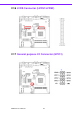
2.8.1 ATX soft power switch ((JFP1+JFP2/ PWR_SW))
If your computer case is equipped with an ATX power supply, you should connect the
power on/off button on your computer case to ((JFP1+JFP2/ PWR_SW)), for conve-
nient power on and off.
2.8.2 Reset (JFP1+JFP2/ RESET)
Many computer cases offer the convenience of a reset button. Connect the wire for
the reset button.
2.8.3 HDD LED (JFP1+JFP2/ HDDLED)
You can connect an LED to connector (JFP2/HDDLED) to indicate when the HDD is
active.
2.8.4 External speaker (JFP1+JFP2/ SPEAKER)
((JFP1+JFP2/ SPEAKER)) is a 4-pin connector for an external speaker. If there is no
external speaker, the AIMB-214 provides an onboard buzzer as an alternative. To
enable the buzzer, set pins 7-10 as closed.
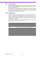
2.8.5 Power LED and keyboard lock connector (JFP3 / PWR_LED &
KEY LOCK)
(JFP3 / PWR_LED & KEY LOCK) is a 5-pin connector for the power on LED and Key
Lock function. Refer to Appendix B for detailed information on the pin assignments.
The Power LED cable should be connected to pin 1-3. The key lock button cable
should be connected to pin 4-5.
There are 3 modes for the power supply connection. The first is “ATX power mode”;
the system turns on/off by a momentary power button. The second is “AT Power
Mode”; the system turns on/off via the power supply switch. The third is another “AT
Power Mode” which makes use of the front panel power switch. The power LED sta-
tus is indicated in the following table:
Table 2.2: ATX power supply LED status (No support for AT power)
Power mode
LED
(ATX Power Mode)
(On/off by
momentary button)
LED
(AT power Mode)
(On/off by switching
power supply)
LED
(AT power Mode)
(On/off by front
panel switch)
PSON1
(on back plane)
jumper setting
pins 2-3 closed pins 1-2 closed
Connect pins 1 & 2 to
panel switch via cable
System On On On On
System Suspend Fast flashes Fast flashes Fast flashes
System Off Slow flashes Off Off