
User Manual


ADAM-6000 Series User Manual 92
1. DI
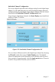
Figure 5.14 is the image when you choose DI mode. At the bottom of the
Status Display area, you can see the digital input value by DI status
LED display. If the digital module you are using supports Invert DI Status
function, there will be Invert signal check box in the Setting area. You
can click the check box to enable or disable that function. Remember to
click the Apply all button for all channels or Apply this button for this
specific channel to complete the configuration. When you enable the
Invert DI Status function, the ADAM-6000 digital module will automati-
cally inverse the digital input value. For example, if the real external sig-
nal value is logic level low, then the DI status LED display will be lit.
All ADAM-6000 digital modules support digital filter, so you can enable
or disable the filter by click the Enable digital filter check box. If you
enable the filter, you can define the minimum acceptable signal width by
the Minimum low signal width and Minimum high signal width text
box. (Unit: ms) The high frequency noise will be removed by this filter.
Remember to click the Apply all button for all channels or Apply this
button for this specific channel to complete the configuration.
2. Counter
When you choose Counter mode, one counter will count the pulse num-
ber of the digital signal from the selected channel, and then record the
count number in the register. The image of the Status Display area looks