
User manual

System Hardware Configuration
Chapter 5
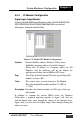
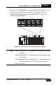
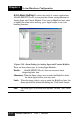
However, the ADAM-5080 is a special module. Each channel is com-
posed of an unsigned long and four bits. For example, if there is a
ADAM-5080 plugged in Slot 6 of ADAM-5000/ TCP system, the
address locations should be:
Figure 5-15: Location of Counter/Frequency Module
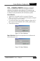
Note: 1st bit: Default ON “1”, available to set ON/OFF to start/stop
counting.
2nd bit: Normal OFF “0”, only accept a pulse ON signal to clear
the counter.
3rd bit: Normal OFF “0”, only tuig ON “1” when counter over-
flow. Users can write "0" to clear the overflow flag.
4th bit: Non used.
ADAM-5000/TCP User’s Manual
5-13