
User manual

System Hardware Configuration
5-3-4
I/O
Module
Canfiguration
Chapter 5
Digital Input Output Module
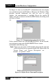
Selecting ADAM-5000 Digital Modules includes ADAM-5050/5051(D)/
5051S/5052/5055S/5056(D)/5056S/5060/5068/5069, user can read
following in- formation from the Utility.
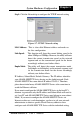
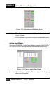
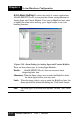
Figure 5-9: Digital I/O Module Configuration
Location: Standard Modbus address.Windows Utility shows
theModbus mapping address of each I/O channel.
(Please refer to chapter 3-5 Assigning address for I/O
Modules) And the addresses will be the indexes for
applying into the data- base of HMI or OPC Server.
Ty p e: Data Type of the I/O channel. The data type of Digital I/O
modules is always “Bit”.
Valu e: The current status on each channel of I/O Module.
The value of digital I/O modules could be “0” (OFF) or
“1” (ON).
Description: Describes the channel numbers and I/O types of the spe-
cific module.
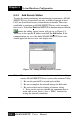
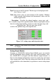
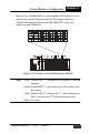
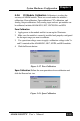
In addition to monitor the current DI/DO status, the Windows
Utility offers a graphical operating interface as figure 5-10. You can
read the Digital input status through the change of the indicator icons.
Oppo- sitely, you can write the digital output status through clicking the
indica- tor icons.
ADAM-5000/TCP
User’s Manual
5-9