Copyright Notice This document is copyrighted, 2001, by Advantech Co., Ltd. All rights are reserved. Advantech Co., Ltd., reserves the right to make improvements to the products described in this manual at any time without notice. No part of this manual may be reproduced, copied, translated or transmitted in any form or by any means without the prior written permission of Advantech Co., Ltd. Information provided in this manual is intended to be accurate and reliable. However, Advantech Co., Ltd.
Product Warranty Advantech warrants to you, the original purchaser, that each of its products will be free from defects in materials and workmanship for two year from the date of purchase. This warranty does not apply to any product which have been repaired or altered by other than repair personnel authorized by Advantech, or which have been subject to misuse, abuse, accident or improper installation. Advantech assumes no liability as a consequence of such events under the terms of this Warranty.
5. photocopy of dated proof of purchase (such as your sales receipt) in a shippable container. A product returned without dated proof of purchase is not eligible for warranty service. Write the RMA number visibly on the outside of the package and ship it prepaid to your dealer.
Technical Support We want you to get the maximum performance from your products. So if you run into technical difficulties, we are here to help. For most frequently asked questions you can easily find answers in your product documentation. Moreover, there are a huge database about troubleshooting and knowledge Base as technical reference on our website. These answers are normally a lot more detailed than the ones we can give over the phone. So please consult this manual or the web site first.
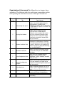
Organization of this manual This Manual has six chapters, three appendices. The following table lists each chapter or appendices with its corresponding title and a brief overview of the topics covered in it. Chapter / Appendix Title Topics Covered Understanding Your System Introduces the suitable applying industries and the position in a SCADA system. Summarize the features and the specification of ADAM-5000/TCP. Explains the functions of the LED indicators.
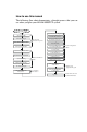
How to use this manual The following flow chart demonstrates a thought process that you can use when you plan your ADAM-5000/TCP system.
Contents Chapter 1 Understanding Your System .................... 1-1 1-1 Introduction ................................................................. 1-2 1-2 Major Features ............................................................ 1-3 1-2-1 Communication Network ...............................................1-3 1-2-2 Modbus/TCP Protocol ....................................................1-3 1-2-3 Hardware Capacity & Diagnostic.................................1-3 1-2-4 Communicating Isolation........
3-3 Mounting ......................................................................3-4 3-3-1 Panel mounting ...........................................................3-4 3-3-2 DIN rail mounting ........................................................3-4 3-4 Wiring and Connections ...........................................3-6 3-4-1 Power supply wiring ...................................................... 3-6 3-4-2 I/O modules wiring .....................................................
Appendix A Design Worksheets ............................A-1 Appendix B Data Formats and I/O Ranges............B-1 B.1 B.2 B.3 B.4 B.5 B.6 B.7 Analog Input Formats ...............................................B-2 Analog Input Ranges - ADAM-5017 ..............................B-4 Analog Input Ranges - ADAM-5018/5018P....................B-5 Analog Input Ranges - ADAM-5017H/5017UH...............B-7 Analog Output Formats ..............................................B-8 Analog Output Ranges...................
Figures Figure 1-1: Apply to System Application ................................................. 1-2 Figure 1-2: ADAM-5000/TCP system & I/O module dimensions ………. 1-7 Figure 1-3: Function block diagram ......................................................... 1-8 Figure 1-4: ADAM-5000/TCP LED Indicators ........................................... 1-8 Figure 2-1: ADAM-5000 I/O Module Selection Chart ............................... 2-3 Figure 2-2: Ethernet Terminal and Cable Connection ......................
Figure 5-19: CJC Calibration .................................................................. 5-16 Figure 5-20: Analog Output Module Calibration ................................... 5-16 Figure 5-21: Firmware Upgrade .............................................................. 5-17 Figure 5-22: Password Setting ............................................................... 5-18 Figure 5-23: Command Emulation .........................................................
Tables Table 2-1: I/O Selection Guidelines .......................................................... 2-2 Table 2-2: I/O Modules Selection Guide .................................................. 2-5 Table 2-3: Power Consumption of ADAM-5000 series ........................... 2-6 Table2-4: Power Supply Specification Table .......................................... 2-7 Table 2-5: Ethernet RJ-45 port Pin Assignment ..................................... 2-8 Table 4-1: I/O module support List……….. .............
Chapter 1 Understanding Your System Using this Chapter If you want to read about Introduction Major Feature Technical Specification LED Status of ADAM-5000/TCP Series main unit Go to page 1-2 1-3 1-6 1-8
Chapter 1 Understanding Your System 1-1 Introduction Undoubtedly, Ethernet connectivity is becoming to a big trend for industrial applications. Longer communication distances, faster communication speeds, and greater advantages attract people into developing their system based upon this network scenario. But there used to be a thresh-old in connecting information layers and field control layers.
Understanding Your System 1-2 Chapter 1 Major Features 1-2-1 Communication Network By adopting a 32-bit RISC CPU, the ADAM-5000/TCP Series has greatly ad- vanced data processing abilities for the user, especially for network com- munications (response time < 5ms).
Chapter 1 Understanding Your System 1-2-4 Communicating Isolation High-speed transient suppressors isolate ADAM-5000/TCP Series Ethernet port from dangerous voltage up to 1500VDC power spikes and avoid surge damage to whole system. 1-2-5 Completed set of I/O modules for total solutions The ADAM-5000/TCP Series uses a convenient backplane system common to the ADAM-5000 series.
Understanding Your System 1-2-8 Chapter 1 Security Setting Though Ethernet technology comes with great benefits in speed and integration, there also exist risks about network invasion from outside. For this reason, a security protection design was built into the ADAM-5000/TCP Series. Once the user has set the password into the ADAM-5000/ TCP firmware, important system configurations (Network, Firmware, Pass- word) can only be changed through password verification.
Chapter 1 Understanding Your System 1-3 Technical specification of ADAM5000/TCP Series System 1-3-1 System • • • • • CPU: ARM 32-bit RISC CPU Memory: 4 MB Flash RAM Operating System: Real-time O/S Timer BIOS: Yes I/O Capacity: 8 slots (ADAM-5000/TCP) 4 slots (ADAM-5000L/TCP) • Status Indicator: Power (3.3V, 5V), CPU, Communication (Link, Collide, 10/100 Mbps, Tx, Rx) • • CPU Power Consumption: 5.0W Reset Push Bottom: Yes 1-3-2 • • • • • • • • Ethernet Communication Ethernet: 10 BASE-T IEEE 802.
Understanding Your System 1-3-4 • • Mechanical Case: KJW with captive mounting hardware Plug-in Screw Terminal Block: Accepts 0.5 mm 2 to 2.
Chapter 1 Understanding Your System 1-3-9 Basic Function Block Diagram Figure 1-3: Function block diagram 1-4 LED Status of ADAM-5000/TCP Series main unit There are eight LEDs on the ADAM-5000/TCP Series front panel.
Understanding Your System Chapter 1 (1) 3.3V: Red indicator. This LED is normal on when ARM CPU is pow- ered on. (2) 5V: Red indicator. This LED is normal on when ADAM-5000/TCP Series system is powered on. Run: Green indicator. This LED is regularly blinks whenever the ADAM-5000/TCP Series system is running. Link: Green Indicator. This LED is normal on whenever the ADAM5000/TCP’s Ethernet wiring is connected. Tx: Green indicator.
Chapter 2 Selecting Your Hardware Components System Design Flow Chart System Hardware Configuration Select I/O Module Install Utility Software Select Power Supply Selecting Your Hardware Component Select Link Terminal & Cable I/O Module Configuration Network Setting Select Operator Interface System Configuration Guide I/O Module Calibration Security Setting Determine Proper Environment Terminal Emulation Install Main Unit and Module System Mounting UDP Data Stream Hardware Installation Guide Modbus
Chapter 2 Selecting Your Hardware Components 2-1 Selecting I/O Module To organize an ADAM-5000/TCP Series data acquisition & control system, you need to select I/O modules to interface the main unit with field de- vices or processes that you have previously determined. There are sev- eral things should be considered when you select the I/O modules.
Selecting Your Hardware Components Chapter 2 Advantech provides 15 types of ADAM-5000 I/O modules for various applications so far. The figure 2-1 and table 2-2 will help you to slect the ADAM-5000 I/O modules quickly and easily. 5051 Digital Input Digital Input Module (16ch.) 5051D Digital Input Module With LED (16 ch.) 5051S Isolated DI Module with LED (16 ch.) 5052 Isolated DI Module (8ch.) 5056 Digital Output Module (16 ch.) 5056D Digital Output Module with LED (16 ch.
Chapter 2 Selecting Your Hardware Components Module Resolution Input Channel Sampling Rate Analog Input Analog Output Digital Input and Digital Output Counter (32bit) COMM ADAM5013 16 bit ADAM5018 16 bit ADAM5018P 16 bit ADAM5024 - 8 8 8 7 7 - 10 8K 200K 10 10 - Voltage Input - ±150 mV ±500 mV ±1 V ±5 V ±10 V ±250 mV ±500 mV ±1 V ±5 V ±10 V V +10V V ±10 V ±15 mV ±50 mV ±100 mV ±500 mV ±1 V ±2.5 V ±15 mV ±50 mV ±100 mV ±500 mV ±1 V ±2.
Chapter 2 Selecting Your Hardware Components Module Analog Input Analog Output Digital Input and Digital Output Count-er (32-bit) COM-M Resolution Input Channel Sampling Rate Voltage Input Current Input Direct Sensor Input Resolution Voltage Output Current Output Digital Input Channels Digital Output Channels Channels Input Frequency Mode Channels Type Isolation Analog Output Digital Input and Digital Output Count-er (32bit) COM-M Isolation - - - - - - - - ADAM-5055S Channels Type ADAM-50
Chapter 2 2-2 Selecting Your Hardware Components Selecting Power Supply ADAM-5000/TCP S e r i e s system works under unregulated power source be- tween +10 and +30 VDC. When you arrange different I/O modules on ADAM-5000/TCP’s back plant, it may require comparable power supply. Use the following steps as guidelines for selecting a power supply for your ADAM-5000/TCP system. • Refer to table 2.3 to check the power consumption of ADAM-5000/ TCP Series main unit and each I/O module.
Selecting Your Hardware Components Chapter 2 ‚ Calculate the Summary of the whole system’s power consumption. For example, there are following items in your system. ADAM-5000/TCP * 3 & ADAM-5024 * 4 & ADAM-5017 * 6 & ADAM-5068 * 5 & ADAM-5050 * 5 & ADAM-5080 * 4 ò The power consumption is: 5W * 3 + 2.9W * 4 + 1.25 * 6 + 1.8W * 5 + 1.2W * 5 + 1.5W * 4 = 55.1W ƒ Selet a suitable power supply from Table2.
Chapter 2 Selecting Your Hardware Components 2-3 Selecting Link Terminal and Cable Ethernet Network Use the RJ-45 connector to connect the Ethernet port of the ADAM5000/TCP Series to the Hub. The cable for connection should be Category 3 (for10Mbps data rate) or Category 5 (for 100Mbps data rate) UTP/STP cable, which is compliant with EIA/TIA 586 specifications. Maximum length between the Hub and any ADAM-5000/TCP Series is up to 100 meters (approx.
Selecting Your Hardware Components Chapter 2 Serial Network The system uses screw terminal for RS-485 twisted pair connection as a data gateway between Ethernet Sever and serial Modbus devices. See Figure 2-3. The following information must be considered. 1. Twisted-pair wire compliant with EIA-422 or EIA-485 standards, which contains 24 AWG thin copper conductor with copper mesh and aluminum foil for shielding. 2. Always use a continuous length of wire, do not combine wires to attain needed length. 3.
Chapter 2 Selecting Your Hardware Components 2-4 Selecting Operator Interface To complete your data acquisition and control system, selecting the operator interface is necessary. Adopting by Modbus/TCP Protocol, ADAM-5000/TCP Series exhibits high ability in system integration for various applications.
Chapter 3 Hardware Installation Guide System Design Flow Chart System Hardware Configuration Select I/O Module Install Utility Software Select Power Supply Selecting Your Hardware Component Select Link Terminal & Cable I/O Module Configuration Network Setting Select Operator Interface System Configuration Guide I/O Module Calibration Security Setting Determine Proper Environment Terminal Emulation Install Main Unit and Module System Mounting UDP Data Stream Hardware Installation Guide Modbus Data
Chapter 3 Hardware Installation Guide 3-1 Determining the proper environment Before you start to install the ADAM-5000/TCP Series system, there are some- thing needed to check.
Hardware Installation Guide 3-2 Chapter 3 Installing your main unit and module When inserting modules into the system, align the PC board of the mod- ule with the grooves on the top and bottom of the system. Push the module straight into the system until it is firmly seated in the back plane connector (see figure 3-1). Once the module is inserted into the system, push in the retaining clips located at the top and bottom of the module to firmly secure the module to the system (see figure 3-2).
Chapter 3 Hardware Installation Guide 3-3 Mounting The ADAM-5000/TCP Series system can be installed on a panel or on a DIN rail. 3-3-1 Panel mounting Mount the system on the panel horizontally to provide proper ventila- tion. You cannot mount the system vertically, upside down or on a flat horizontal surface. A standard #7 tatting screw (4 mm diameter) should be used.
Hardware Installation Guide Chapter 3 Figure 3-4: ADAM-5000/TCP DIN rail mounting Figure 3-5: Secure ADAM-5000/TCP System to a DIN rail ADAM-5000/TCP User’s Manual 3-5
Chapter 3 Hardware Installation Guide 3-4 Wiring and Connections This section provides basic information on wiring the power supply, I/O units, and network connection. 3-4-1 Power supply wiring Although the ADAM-5000/TCP Series systems are designed for a standard industrial unregulated 24 V DC power supply, they accept any power unit that supplies within the range of +10 to +30 VDC.
Hardware Installation Guide 3-4-2 Chapter 3 I/O modules wiring The system uses a plug-in screw terminal block for the interface between I/O modules and field devices. The following information must be considered when connecting electrical devices to I/O modules. 1. The terminal block accepts wires from 0.5 mm to 2.5 mm. 2. Always use a continuous length of wire. Do not combine wires to make them longer. 3. 4. 5. 6. Use the shortest possible wire length. Use wire trays for routing where possible.
Chapter 3 Hardware Installation Guide 3-4-3 System Network Connections Ethnet Network The ADAM-5000/TCP Series has an Ethernet communication port allowed you to program, configure, monitor, and integrate into the SCADA system. The figure 3-8 is a guideline to complete the system network connection.
Hardware Installation Guide Chapter 3 Serial Network Working as an Ethernet Data Gateway, the ADAM-5000/TCP Series provides an RS-485 interface to integrate serial devices for various applications. Adopting by Modbus standard protocol, it solves the communication problem between different networks and different devices. Mean while, users can extend their system scope by integrating up to 32 nodes of ADAM-5511 or other Modbus products, such as meters, card readers, loadcell, and so on.
Chapter 3 Hardware Installation Guide 3-5 Assigning address for I/O Modules Basing on Modbus standard, the addresses of the I/O modules you place into the ADAM-5000/TCP Series system are defined by a simple rule. Please refer the figures 3-9 to map the I/O address. Figure 3-10: I/O Modules Address Mapping For example, if there is a ADAM-5024 (4-channel AO Module) in slot 2, the address of this module should be 40017~40020. Note: ADAM-5080 is a special 4-channel counter module.
4 I/O modules
This manual introduces the detail specifications functions and application wiring of each ADAM-5000 I/O modules.To organize an ADAM-5000 series and ADAM-5510 Series Controller, you need to select I/O modules to interface the main unit with field devices or processes that you have previously determined. Advantech provides 20 types of ADAM5000 I/O modules for various applications so far. Following table is the I/ O modules support list we provided for user’s choice.
Chapter 5 System Hardware Configuration System Design Flow Chart System Hardware Configuration Select I/O Module Install Utility Software Select Power Supply Selecting Your Hardware Component Select Link Terminal & Cable I/O Module Configuration Network Setting Select Operator Interface System Configuration Guide I/O Module Calibration Security Setting Determine Proper Environment Terminal Emulation Install Main Unit and Module System Mounting UDP Data Stream Hardware Installation Guide Modbus Data
Chapter 5 System Hardware Configuration This chapter explains how to use Windows Utility to configure the ADAM-5000/TCP Series system for various applications. Users can learn the hardware connection, software installation, communication setting and every procedure for system configuration from these sections. 5-1 System Hardware Configuration As we mentioned in chapter 3-1, you will need following items to complete your system hardware configuration.
System Hardware Configuration 5-2 Chapter 5 Install Utility Software on Host PC ADAM-5000/TCP Series Systems come packaged with a Utility CD, containing ADAM Product series Utilities as system configuration tool. While you Insert the CD into the CD drive (e.g. D:) of the host PC, the Utility soft- ware setup menu will start up automatically. Click the ADAM-5000/TCP Series icon to execute the setup program.
Chapter 5 System Hardware Configuration The top of the operation screen consists of a function menu and a tool bar for user’s commonly operating functions. Function menu Item File contents “Exit” Function, using to exit this Utility program. Item Tool contents functions as below: Add Remote 5000/TCP : Create a new ADAM-5000/TCP located in other Ethernet domination, both available to local LAN and Internet application.
System Hardware Configuration Chapter 5 Tool Bar There are five push buttons in the tool bar. Figure 5-3: Tool Bar 5-3-2 Ethernet Network Setting As the moment you start up this Windows Utility, it will search all ADAM5000/TCP Series on the host PC’s domination Ethernet network automatically. Then the tree-structure display area will appeal with the searched units and the relative IP address.
Chapter 5 System Hardware Configuration See Figure 5-4, there are also Host PC’s information in the status display area, include host name and IP address. Moreover, the Windows Utility provides network connection test tool for user to verify whether the communication is workable. Key-in the specific IP address you want to connect and click the PING button, the testing result will show as Figure 5-5.
System Hardware Configuration Chapter 5 Step2: Click the Network tip to configure the TCP/IP network setting Figure 5-7: TCP/IP Network setting MAC Address: This is also called Ethernet address and needs no fur- ther configuration. Link Speed: This function will show the current linking speed to be either 10Mbps or 100Mbps. However, the utility will autodetect the current transmission speed on the network segment and set the transmission speed for the device accordingly without your further efforts.
Chapter 5 System Hardware Configuration 5-3-3 Add Remote Station To meet the remote monitoring and maintenance requirements, ADAM5000/TCP Series System does not only available to operate in local LAN, but also allowed to access from internet or intranet. Thus users would able to configure an ADAM-5000/TCP Series easily no matter how far it is. Select item Tool\Add 5000/TCP in function menu or click the button, the adding station screen will pop up as Figure 5-8.
System Hardware Configuration 5-3-4 Chapter 5 I/O Module Canfiguration Digital Input Output Module Selecting ADAM-5000 Digital Modules includes ADAM-5050/5051(D)/ 5051S/5052/5055S/5056(D)/5056S/5060/5068/5069, user can read following in- formation from the Utility. Figure 5-9: Digital I/O Module Configuration Location: Standard Modbus address.Windows Utility shows theModbus mapping address of each I/O channel.
Chapter 5 System Hardware Configuration Figure 5-10: Operating and Indicating Icons Note: 1. The indicator icons are only available to click for digital output channel. 2. The hexadecimal code will be calculated automatically for any status. Analog Input Module Selecting ADAM-5000 Analog Input Modules includes ADAM-5013/ 5017(H)/5018s, users can read following information from the Utility. Figure 5-11: Current Analog Input Status Location: Standard Modbus address.
System Hardware Configuration Chapter 5 Type: Data type of the I/O channel. The data type of analog Input modules is always “word”. Value: The current status on each channel of I/O modules. Windows Utility provides both decimal and hexadecimal values used for different applications. Description: Describes the channel numbers, sensor types, and mea- surement range of the specified module. Before acquiring the current data of an analog input module, you have to select the input range and integration time.
Chapter 5 System Hardware Configuration Figure 5-13: Analog Module Configuration Screen Note: Initial Setting function: Adjust a initial output value you want to set to the specified channel and click the set as initial button, the channel will output the same value each time when system is initial. Counter/Frequency Module Selecting an ADAM-5080 Counter/Frequency Module, users also can read the information about location, type, value, and description from four individual channel configuration screens.
System Hardware Configuration Chapter 5 However, the ADAM-5080 is a special module. Each channel is composed of an unsigned long and four bits. For example, if there is a ADAM-5080 plugged in Slot 6 of ADAM-5000/ TCP system, the address locations should be: Figure 5-15: Location of Counter/Frequency Module Note: 1st bit: Default ON “1”, available to set ON/OFF to start/stop counting. 2nd bit: Normal OFF “0”, only accept a pulse ON signal to clear the counter.
Chapter 5 System Hardware Configuration 5-3-5 Alarm Setting To satisfy the needs of various applications, ADAM-5000/TCP Series system provides Alarm setting function for Analog Input and Counter Module. Users can set High/Low limit value to identify the alarm status and trig- ger a digital output as an event handling function.
System Hardware Configuration 5-3-6 Chapter 5 I/O Module Calibration Calibration is to adjust the accuracy of ADAM module. There are several modes for module’s calibration: Zero calibration, Span calibration, CJC calibration, and Analog Output calibration. Only analog input and out- put modules can be calibrated, includes ADAM-5013, 5017, 5017H, 5018 and 5024. Zero Calibration 1. Apply power to the module and let it warm up for 30 minutes. 2.
Chapter 5 System Hardware Configuration CJC Calibration 1. Prepare an accurate voltage source. 2. Run the zero calibration and span calibration function. 3. Use a temperature emulation device (such as Micro-10) to send a temperature signal to the ADAM module and then compare this signal with the value from the ADAM module. If the value is different from the signal, adjust the CJC value to improve it.
System Hardware Configuration 5-3-7 Chapter 5 Firmware Update ADAM-5000/TCP Series supports all ADAM-5000 series I/O modules and nec- essary operating function so far. But Advantech always provides better hardware and software functions to improve the perfect DA&C systems. Therefore, users will need to upgrade the firmware of ADAM-5000/TCP Series sometime. Select the Firmware Upgrade tab and click Browsing to find the specific firmware (*.bin) for upgrade.
Chapter 5 System Hardware Configuration 5-3-8 Security Setting Though the technology of Ethernet discovered with great benefits in speed and integration, there also exist risk about network invading form anywhere. For the reason, the security protection design has built-in ADAM-5000/TCP Series system. Once user setting the password into the ADAM-5000/TCP Series firmware, the important system configurations (Net- work, Firmware, Password) are only allowed to be changed by password verification.
System Hardware Configuration 5-3-9 Chapter 5 Terminal Emulation You can issue commands and receive response by clicking the Terminal button on the tool bar. There are two kinds of command format supported by this emulating function. Users can choose ASCII or Hexadecimal mode as their communication base. If the ASCII mode has been selected, the Windows Utility will translate the request and response string both in Modbus and ASCII format.
Chapter 5 System Hardware Configuration 5-3-10 Data Stream Data Stream Configuration In addition to TCP/IP communication protocol, ADAM-5000/TCP Series sup- ports UDP communication protocol to regularly broadcast data to spe- cific host PCs. Click the tip of Data stream, then configure the broadcasting interval and the specific IPs which need to receive data from the specific ADAM5000/TCP Series.
System Hardware Configuration Chapter 5 Figure 5-25: Data Stream Monitoring Select the IP address of the ADAM-5000/TCP Series you want to read data, then click “Start” button. The Utility software will begin to receive the stream data on this operation display.
Chapter 5 System Hardware Configuration 5-3-11 Data Gateway Setting ADAM-5000/TCP Series is designed with an RS-485 Modbus Interface. As a Data Gateway, It integrates serial Modbus devices into Ethernet applica- tion easily. Click the tip of “RS-485/Modbus” to configure the RS-485 network setting with following steps. Figure 5-26: RS-485 Modbus Network Setting 1. Define the parameter of the network, includes Parity, stop bit, Baud Rate (300~115200bps),and Timeout. 2.
Chapter 6 Planning Your Application Program System Design Flow Chart System Hardware Configuration Select I/O Module Install Utility Software Select Power Supply Selecting Your Hardware Component Select Link Terminal & Cable I/O Module Configuration Network Setting Select Operator Interface System Configuration Guide I/O Module Calibration Security Setting Determine Proper Environment Terminal Emulation Install Main Unit and Module System Mounting UDP Data Stream Hardware Installation Guide Modbus D
Chapter 6 Planning Your Application Program 6-1 Introduction After completing the system configuration, you can begin to plan the application program. This chapter introduces two programming tools for users to execute system data acquisition and control. The DLL drivers and command sets provide a friendly interface between your applica- tions and ADAM-5000/TCP Series system.
Planning Your Application Program Function Libraries ADAM5KTCP_ReadCoil ADAM5KTCP_WriteCoil ADAM5KTCP_SendReceive5KTCPCmd ADAM5KTCP_Add5KTCPForStream ADAM5KTCP_ReadStreamData ADAM5KTCP_ReadAlarmInfo ADAM5KTCP_StartStream ADAM5KTCP_StopStream ADAM5KTCP_SetStreamAlarmState ADAM5KTCP_Debug ADAM5KTCP_UDPOpen ADAM5KTCP_UDPClose ADAM5KTCP_SendReceiveUDPCmd ADAM-5000/TCP User’s Manual Chapter 6 Pages 6-16 6-17 6-18 6-19 6-20 6-21 6-22 6-23 6-24 6-25 6-26 6-27 6-28 6-3
Chapter 6 Planning Your Application Program 6-2-2 Programming Flow * Send a command and receiving response by UDP ADAM5KTCP_Open( ) ADAM5KTCP_SendReceiveUDPCmd( ) ADAM5KTCP_UDPOpen( ) ADAM5KTCP_SendReceiveUDPCmd( ) ADAM5KTCP_UDPClose( ) ADAM5KTCP_Close( ) 6-4 ADAM-5000/TCP User’s Manual
Planning Your Application Program Chapter 6 * Send a command and receiving response by TCP ADAM5KTCP_Open( ) ADAM5KTCP_Connect( ) ADAM5KTCP_SendReceive5KTCPCmd( ) ADAM5KTCP_Disconnect( ) ADAM5KTCP_Close( ) ADAM-5000/TCP User’s Manual 6-5
Chapter 6 Planning Your Application Program * To receive stream data coming from ADAM-5000/TCP Series (s) ADAM5KTCP_Open( ) ADAM5KTCP_Add5KTCPForStream( ) hEvent=CreateEvent( ) (A Win32 API) ADAM5KTCP_StartStream( &hEvent ) N hEvent signaled ? Y ADAM5KTCP_ReadStreamData( ) N quit ? Y ADAM5KTCP_StopStream( ) ADAM5KTCP_Close( ) 6-6 ADAM-5000/TCP User’s Manual
Planning Your Application Program Chapter 6 * To receive alarm information from ADAM-5000/TCP(s) ADAM5KTCP_Open( ) ADAM5KTCP_Add5KTCPForStream( ) hEvent=CreateEvent ( ) (A Win32 API) ADAM5KTCP_SetStreamAlarmState(ADAM5KTCP_ReceiveStreamWhenAlarm) ADAM5KTCP_StartStream( &hEvent ) N hEvent signaled ? Y ADAM5KTCP_ReadStreamDatat( ) 1 ADAM5KTCP_ReadAlarmInfo( ) Y N Alarm info buffer is empty? Y N quit ? ADAM5KTCP_StopStream( ) ADAM5KTCP_Close( ) ADAM-5000/TCP User’s Manual 6-7
Chapter 6 Planning Your Application Program * To read coil values ADAM5KTCP_Open( ) ADAM5KTCP_Connect( ) ADAM5KTCP_ReadCoil( ) ADAM5KTCP_Disconnect( ) ADAM5KTCP_Close( ) * To write value to coil ADAM5KTCP_Open( ) ADAM5KTCP_Connect( ) ADAM5KTCP_WriteCoil( ) ADAM5KTCP_Disconnect( ) ADAM5KTCP_Close( ) 6-8 ADAM-5000/TCP User’s Manual
Planning Your Application Program Chapter 6 * To read holding register value ADAM5KTCP_Open( ) ADAM5KTCP_Connect( ) ADAM5KTCP_ReadReg( ) ADAM5KTCP_Disconnect( ) ADAM5KTCP_Close( ) * To write value to holding register ADAM5KTCP_Open( ) ADAM5KTCP_Connect( ) ADAM5KTCP_WriteReg( ) ADAM5KTCP_Disconnect( ) ADAM5KTCP_Close( ) ADAM-5000/TCP User’s Manual 6-9
Chapter 6 Planning Your Application Program 6-2-3 Function Descriptions ADAM5KTCP_Open 6-10 Description: Initiate the “adam5ktcp.dll” for using.
Planning Your Application Program Chapter 6 ADAM5KTCP_Close Description: Terminates using the “adam5ktcp.dll”.
Chapter 6 Planning Your Application Program ADAM5KTCP_Connect Description: Establish a Windows Sockets connection in a specified ADAM-5000/TCP system.
Planning Your Application Program Chapter 6 ADAM5KTCP_Disconnect Description: Disconnect the Windows Sockets connection of the specified ADAM-5000/TCP Syntax: void ADAM5KTCP_Disconnect(void); Parameter: void Return: Please refer to Chapter 6-2-4 “Return Codes” for more detail information ADAM-5000/TCP User’s Manual 6-13
Chapter 6 Planning Your Application Program DAM5KTCP_GetDLLVersion 6-14 Description: Read the version of ADAM-5000/TCP DLL driver Syntax: int ADAM5KTCP_GetDLLVersion(void); Parameter: void Return: 0x150 means Version 1.
Planning Your Application Program Chapter 6 ADAM5KTCP_ReadReg Description: Reads the holding register value at a specified range described in parameters. Syntax: int ADAM5KTCP_ReadReg(char szIP[], WORD wID, WORD wStartAddress, WORD wCount, WORD wData[]); Parameter: szIP[in]: the IP Address of the ADAM-5000/TCP that to be connected wID[in]: the specific device ID for an Modbus/TCP device.
Chapter 6 Planning Your Application Program ADAM5KTCP_WriteReg Description: Write the holding register value at a specified range described in parameters. Syntax: int ADAM5KTCP_WriteReg(char szIP[], WORD wID, WORD wStartAddress, WORD wCount, WORD wData[]); Parameter: szIP[in]: the IP Address of the ADAM-5000/TCP that to be connected wID[in]: the specific device ID for an Modbus/TCP device.
Planning Your Application Program Chapter 6 ADAM5KTCP_ReadCoil Description: Read the coils value at a specified range described in parameters. Syntax: int ADAM5KTCP_ReadCoil(char szIP[], WORD wID, WORD wStartAddress, WORD wCount, BYTE byData[]); Parameter: szIP[in]: the IP Address of the ADAM-5000/TCP that to be connected wID[in]: the specific device ID for an Modbus/TCP device.
Chapter 6 Planning Your Application Program ADAM5KTCP_WriteCoil Description: Write the coils value at a specified range described in parameters. Syntax: int ADAM5KTCP_WriteCoil(char szIP[], WORD wID, WORD wStartAddress, WORD wCount, BYTE byData[]); Parameter: szIP[in]: the IP Address of the ADAM-5000/TCP that to be connected wID[in]: the specific device ID for an Modbus/TCP device.
Planning Your Application Program Chapter 6 ADAM5KTCP_SendReceive5KTCPCmd Description: This function is designed for user’s convenience, accepting the ASCII format string as a command. Then transform it to meet the Modbus/TCP specification.
Chapter 6 Planning Your Application Program ADAM5KTCP_Add5KTCPForStream 6-20 Description: Assign a specified ADAM-5000/TCP to send stream data to the PC Syntax: int ADAM5KTCP_Add5KTCPForStream(char szIP[]); Parameters: szIP[in]: the IP Address of the ADAM-5000/TCP that assign to send stream data to the PC Return: Please refer to Chapter 6-2-4 “Return Codes” for more detail information ADAM-5000/TCP User’s Manual
Planning Your Application Program Chapter 6 ADAM5KTCP_ReadStreamData Description: Receive stream data that comes from the specific ADAM-5000/TCP Syntax: int ADAM5KTCP_ReadStreamData(char szIP[], struct _StreamData *pStreamData); Parameters: szIP[in]: to specify the IP Address for a user to receive the stream data *pStreamData[out]: the stream data stored in _StreamData structure Please refer to Chapter 6-2-5 “Data Structure” for more detail information about _StreamData structure.
Chapter 6 Planning Your Application Program ADAM5KTCP_ReadAlarmInfo Description: Receive alarm information that comes from the specific ADAM-5000/TCP Syntax: int ADAM5KTCP_ReadAlarmInfo (struct _AlarmInfo *pAlarmInfo); Parameters: *pAlarmInfo[out]: Return: 6-22 the alarm information stored in _AlarmInfo structure Please refer to Chapter 6-2-5 “Data Structure” for more detail information about _AlarmInfo structure.
Planning Your Application Program Chapter 6 ADAM5KTCP_StartStream Description: Instruct the PC to start receiving stream data from the ADAM-5000/TCP Syntax: int ADAM5KTCP_StartStream (HANDLE *EventFromApp); Parameters: *EventFromApp: Return: the event object that would pass down to ADAM5KTCP.DLL This event object would be signaled either a stream data send to PC or an alarm status change in ADAM5000/TCP.Please refer to ADAM5KTCP_SetStream AlarmState for more detail information.
Chapter 6 Planning Your Application Program ADAM5KTCP_StopStream 6-24 Description: Instruct the PC to stop receiving stream data Syntax: int ADAM5KTCP_StopStream( ); Parameters: void Return: void ADAM-5000/TCP User’s Manual
Planning Your Application Program Chapter 6 ADAM5KTCP_SetStreamAlarmState Description: Set the criterion to signal the event object Syntax: int ADAM5KTCP_SetStreamAlarmState(WORD wStreamAlarmState); Parameters: wStreamAlarmState[in]: When assigned to ADAM5KTCP_Receive StreamIngoreAlarm: means the ADAM5KTCP.DLL always signals event object when any stream data comes from an ADAM-5000/TCP. Then the application can receive the stream data by calling “ADAM5KTCP_ReadStreamData()” function.
Chapter 6 Planning Your Application Program ADAM5KTCP_Debug Description: Trace the executive information about streaming data mechanism in ADAM5KTCP.DLL (It is convenient to troubleshooting of user’s applications.) Syntax: int int ADAM5KTCP_Debug(int *iMatchIndex, *iReceiveCount, int *iThreadRun, int *iTotalStream, char szFromIP[]); Parameters: *iMatchIndex[out]: indicating which ADAM-5000/TCP cause signaling the event object 0 means the first ADAM-5000/TCP, 1 means second, 2 means third, and so on.
Planning Your Application Program Chapter 6 ADAM5KTCP_UDPOpen Description: Opens a UDP socket and sets the timeout of send/ receive interval to prepare send a command to ADAM-5000/TCP by UDP. Syntax: int ADAM5KTCP_UDPOpen(int iSendTimeout, int iReceiveTimeout); Parameters: iSendTimeout[in]: the specified timeout interval for sending a command string to the ADAM-5000/TCP by UDP. iReceiveTimeout[in]: the specified timeout interval for receiving a re- sponse string from the ADAM-5000/TCP by UDP.
Chapter 6 Planning Your Application Program ADAM5KTCP_UDPClose Description: opened by Syntax: Parameters: Return: 6-28 Closes the UDP socket that has been “ADAM5KTCP_UDPOpen()”. int ADAM5KTCP_UDPClose(); Void Please refer to Chapter 6-2-4 “Return Codes” for more detail information.
Planning Your Application Program Chapter 6 ADAM5KTCP_SendReceiveUDPCmd Description: Sends a command to ADAM-5000/TCP and receives the response by UDP Syntax: int ADAM5KTCP_SendReceiveUDPCmd(char szIP[], char szSend[], char szReceive[]); Parameters: szIP[in]: szSend[in]: szReceive[out]: the IP Address of the ADAM-5000/TCP that send/ receive the command/response the string in ASCII format that send to the ADAM5000/TCP the string in ASCII format that response from the ADAM-5000/TCP ADAM-5000/TCP User’
Chapter 6 Planning Your Application Program 6-2-4 Return Codes Using these function libraries, you can read the error message and the against response from the returning codes.
Planning Your Application Program Chapter 6 6-2-5 Data Structure struct _StreamData { WORD DIO[8]; // DI/DO data for Slot0, Slot1,....
Chapter 6 Planning Your Application Program 6-3 ADAM-5000/TCP Command ADAM-5000/TCP system accepts a command/response form with the host computer. When systems are not transmitting they are in listen mode. The host issues a command to a system with a specified address and waits a certain amount of time for the system to respond. If no response arrives, a time-out aborts the sequence and returns control to the host.
Planning Your Application Program Chapter 6 And the response should be: Figure 6-2: Response Comment Structure 6-3-2 Modbus Function Code Introduction To full-fill the programming requirement, there is a series of function code standard for user’s reference... Code (Hex) Name Usage 01 Read Coil Status Read Discrete Output Bit 02 Read Input Status Read Discrete Input Bit 03 Read Holding Registers 04 Read Input Registers Read 16-bit register.
Chapter 6 Planning Your Application Program Example: Read coil number 1 to 8 (address number 10001 to 10008) from ADAM-5000/TCP 01 01 00 01 00 08 Response message format for function code 01: Command Body Station Address Example: Function Code Byte Count Data Data … Coils number 2 and 7 are on, all others are off. 01 01 01 42 In the response the status of coils 1 to 8 is shown as the byte value 42 hex, equal to 0100 0010 binary.
Planning Your Application Program Chapter 6 Function Code 03/04 The function code 03 or 04 is used to read the binary contents of input registers Request message format for function code 03 or 04: Command Body Station Address Function Start Code Address Start Requested Requested Address Number of Register Number of Register High Byte Low Byte Example: High Byte Low Byte Read Analog inputs #1 and #2 in addresses 40001 to 40004 as floating point value from ADAM-5000/TCP 01 04 00 01 00 04 Response me
Chapter 6 Planning Your Application Program Response message format for function code 05: The normal response is an echo of the query, returned after the coil state has been forced. Command Body Station Function Address Code Coil Address High Byte Coil Address Low Byte Force Force Data Data High Byte Low Byte Function Code 06 Presets integer value into a single register.
Planning Your Application Program Chapter 6 Response message format for function code 08: Command Body StationAddress Example: FunctionCode Data bytes received 01 08 00 02 00 04 Function Code 15 (0F hex) Forces each coil in a sequence of coils to either ON or OFF.
Chapter 6 Planning Your Application Program Function Code 16 (10 hex) Preset values into a sequence of holding registers. Request message format for function code 16: Command Body Station Address Function Code Requested Start Start Number of Address Address Register High Byte Low Byte High Byte Requested Number of Register Low Byte Byte Count Data Example: Preset constant #1 (address 40009) to 100.0 in ADAM-5000/TCP.
Planning Your Application Program 6-4 Chapter 6 Apply with ASCII Command for ADAM-5000/TCP System For users do not familiar to Modbus protocol, Advantech offers a func- tion library as a protocol translator, integrating ASCII command into Modbus/TCP structure. Therefore, users familiar to ASCII command can access ADAM-5000/TCP easily. Before explaining the structure of ASCII command packed with Modbus/TCP format.
Chapter 6 Planning Your Application Program Every command set category starts with a command summary of the particular type of module, followed by datasheets that give detailed information about individual commands. Although commands in different subsections sometime share the same format, the effect they have on a certain module can be completely differ- ent than that of another.
Planning Your Application Program Chapter 6 %aannccff Name Configuration Description Sets RS-485 network baud rate and checksum status for a specified ADAM-5000/TCP system Syntax %aannccff(cr) % is a delimiter character. aa (range 00-FF) represents the 2-character hexadecimal Modbus network address of the ADAM-5000/ TCP system you want to configure. nn is reserved for system use. Its default value is 00h. cc represents the baud rate code.
Chapter 6 Planning Your Application Program mal Modbus network address of an ADAM-5000/ TCP system. (cr) is the terminating character, carriage return (0Dh). Example Note: command: %01000A40(cr) response: !01(cr) The ADAM-5000/TCP system with address 01h is configured to a baud rate of 115.2 Kbps and with checksum generation or validation. The response indicates that the command was received. Wait 7 seconds to let the new configuration setting take effect before issuing a new command to the system.
Planning Your Application Program Chapter 6 $aa2 Name Configuration Status Description Returns the configuration status for a specified system module. Syntax $aa2(cr) $ is a delimiter character. aa (range 00-FF) represents the 2-character hexadecimal Modbus network address of the ADAM-5000/ TCP system you want to interrogate. 2 is the Configuration Status command. (cr) is the terminating character, carriage return (0Dh). Response !aaccff(cr) if the command is valid.
Chapter 6 Planning Your Application Program Example 6-44 command: $012(cr) response: !010600(cr) The command requests the ADAM-5000/TCP sys- tem at address 01h to send its configuration status. The ADAM-5000 system at address 01h responds with a baud rate of 9600 bps and with no checksum function or checksum generation.
Planning Your Application Program $aaM Name Description Syntax Response Example Chapter 6 Read Module Name Returns the module name from a specified ADAM5000/TCP system. $aaM(cr) $ is a delimiter character. aa (range 00-FF) represents the 2-character hexadecimal address of the ADAM-5000/TCP system you want to interrogate. M is the Module Name command. (cr) is the terminating character, carriage return (0Dh). !aa5000(cr) if the command is valid. ?aa(cr) if an invalid operation was entered.
Chapter 6 Planning Your Application Program $aaF Name Description Syntax Response Example Read Firmware Version Returns the firmware version code from a specified ADAM-5000/TCP system. $aaF(cr) $ is a delimiter character. aa (range 00-FF) represents the 2-character hexadecimal address of the ADAM-5000/TCP system you want to interrogate. F is the Firmware Version command. (cr) is the terminating character, carriage return (0Dh). !aa(version)(cr) if the command is valid.
Planning Your Application Program $aaT Name Description Syntax Response Example Chapter 6 Read I/O Type Returns the I/O module no. of all slots for a specified ADAM-5000/TCP system. $aaT(cr) $ is a delimiter character. aa (range 00-FF) represents the 2-character hexadecimal address of the ADAM-5000/TCP system you want to interrogate. T is the I/O Module Types command. (cr) is the terminating character, carriage return (0Dh). !aabbccddee(cr) if the command is valid.
Chapter 6 Planning Your Application Program 6-4-3 Analog Input Command Set Before setting commands, the user needs to know the type of main unit being used. If ADAM-5000/485 is being used, the “i” in Si can be set at 0 to 3. If ADAM-5000E or ADAM-5000/TCP is being used, the “i” in Si can be set at 0 to 7.
Planning Your Application Program Chapter 6 Command Syntax Command Name Description $aaSiER Initialize EEPROM Data Initializes all EEPROM data in a specified RTD input module to their default values $aaSi5mm Enable/Disable Channels for Multiplexing Enables/disables multiplexing simultaneously for separate channels of the specified input module $aaSi6 Read Channels Status Asks a specified input module to return the status of all channels $aaSi0 RTD Span Calibration Calibrates a specified RTD i
Chapter 6 Planning Your Application Program $aaSiArrff Name Description Syntax Response Example 6-50 RTD Configuration Sets slot index, input range, data format and integration time for a specified RTD input module in a specified system. $aaSiArrff(cr) $ is a delimiter character. aa (range 00-FF) represents the 2-character hexadecimal address of the ADAM-5000/TCP system you want to configure. Si identifies the desired slot i (i:0 to 7). A represents the I/O module configuration command.
Planning Your Application Program $aaSiB Name Description Syntax Response Example Chapter 6 RTD Configuration Status Returns the configuration parameters for a specified RTD input module in a specified system. $aaSiB(cr) $ is a delimiter character. aa (range 00-FF) represents the 2-character hexadecimal address of the ADAM-5000/TCP system you want to interrogate.
Chapter 6 Planning Your Application Program $aaSi Name All RTD Data In Description Returns the input values of all channels of a specified RTD input module in a specified system in engineering units only. Syntax $aaSi(cr) $ is a delimiter character. aa (range 00-FF) represents the 2-character hexadecimal Modbus network address of the ADAM-5000/ TCP system you want to interrogate. Si is the I/O slot of the ADAM-5000/TCP system you want to read. (cr) is the terminating character, carriage return (0Dh).
Planning Your Application Program Chapter 6 (cr) is the terminating character, carriage return (0Dh). Example command: $01S3(cr) response: >+80.01 +20.00 -40.12(cr) The command requests the RTD input module in slot 3 of the ADAM-5000/TCP system at address 01h to return the input values of all channels. The RTD input module responds with input values of all channels in sequence from 0 to 2: +80.01° C, +20.00° C, 40.12° C.
Chapter 6 Planning Your Application Program $aaSiCj Name Specified RTD Data In Description Returns the input value of a specified channel for a specified RTD input module of a specified system in engineering units only. Syntax $aaSiCj(cr) $ is a delimiter character. aa (range 00-FF) represents the 2-character hexadecimal Modbus network address of the ADAM-5000/ TCP system you want to interrogate.
Planning Your Application Program Chapter 6 (cr) is the terminating character, carriage return (0Dh). Example command: $01S3C0(cr) response: >+80.01(cr) The command requests the RTD input module in slot 3 of the ADAM-5000/TCP system at address 01h to return the input value of channel 0. The RTD input module responds that the input value of channel 0 is +80.01° C.
Chapter 6 Planning Your Application Program $aaSiER Name Initialize EEPROM Data Description Initializes all EEPROM data in a specified analog input module to their default values. This command is sent following a failed attempt to calibrate a module (the module shows no effect from an attempted calibration). Following initialization, the problem module should readily accept calibration. Syntax $aaSiER(cr) $ is a delimiter character.
Planning Your Application Program $aaSi5mm Name Description Syntax Response Example Chapter 6 Enable/Disable Channels for multiplexing Enables/Disables multiplexing for separate channels of the specified input module $aaSi5mm(cr) $ is a delimiter character. aa (range 00-FF) represents the 2-character hexadecimal address of the ADAM-5000/TCP system. Si identifies the I/O slot of the system. 5 represents the enable/disable channels command. mm are two hexadecimal values.
Chapter 6 Planning Your Application Program $aaSi6 Name Description Syntax Response Example 6-58 Read Channels Status Asks a specified input module to return the status of all channels $aaSi6(cr) $ is a delimiter character. aa (range 00-FF) represents the 2-character hexadecimal address of the ADAM-5000/TCP system you want to interrogate. Si identifies the I/O slot of the system you want to read channels status. The channel status defines whether a channel is enabled or disabled.
Planning Your Application Program $aaSi0 Name Description Syntax Response. Chapter 6 RTD Span Calibration Calibrates a specified RTD input module of a specified system to correct for gain errors. $aaSi0(cr) $ is a delimiter character. aa (range 00-FF) represents the 2-character hexadecimal address of the ADAM-5000/TCP system which contains the RTD module. Si identifies the slot i (i:0 to 7) containing the RTD module to be calibrated. 0 represents the span calibration command.
Chapter 6 Planning Your Application Program $aaSi1 Name Description Syntax Response RTD Zero Calibration Calibrates a specified RTD input module of a specified system to correct for offset errors. $aaSi1(cr) $ is a delimiter character. aa (range 00-FF) represents the 2-character hexadecimal address of the ADAM-5000/TCP system which contains the module which is to be calibrated. Si identifies the slot i (i:0 to 7) containing the RTD module to be calibrated. 1 represents the zero calibration command.
Planning Your Application Program Chapter 6 $aaSi2 Name RTD Self Calibration Description Causes a specified RTD input module of a specified system to do a self- calibration. Note: This command is for use when RTD Zero and Span calibration commands have been tried and had no effect. A user first issues an RTD self-calibration command, and then issues zero and span calibration commands. Syntax $aaSi2(cr) $ is a delimiter character.
Chapter 6 Planning Your Application Program aa (range 00-FF) represents the 2-character hexadecimal Modbus network address of an ADAM-5000/ TCP system. (cr) is the terminating character, carriage return (0Dh).
Planning Your Application Program Chapter 6 ADAM-5017/5018 Analog Input Command Set Command Syntax Command Name Description $aaSiArrff Configuration Sets slot index, input range, data format and integration time for a specified analog input module in a specified system. $aaSiB Configuration Status Returns the configuration parameters for a specified analog input module of a specified system.
Chapter 6 Planning Your Application Program $aaSiArrff Name Description Syntax Configuration Sets slot index, input range, data format and integration time for a specified analog input module in a specified system. $aaSiArrff(cr) $ is a delimiter character. aa (range 00-FF) represents the 2-character hexadecimal address of the ADAM-5000/TCP system you want to configure. Si identifies the I/O slot you want to configure. A is I/O module configuration command.
Planning Your Application Program Response Example Note: Chapter 6 !aa(cr) if the command is valid. ?aa(cr) if an invalid operation was entered. There is no response if the module detects a syntax error or communication error or if the specified ad- dress does not exist. ! delimiter character indicating a valid command was received. ? delimiter character indicating the command was invalid. aa (range 00-FF) represents the 2-character hexadecimal address of an ADAM-5000/TCP system.
Chapter 6 Planning Your Application Program $aaSiB Name Description Syntax Response Example 6-66 Configuration Status Returns the configuration status parameters for a specified analog input module of a specified system. $aaSiB(cr) $ is a delimiter character. aa (range 00-FF) represents the 2-character hexadecimal address of the ADAM-5000/TCP system you want to interrogate. Si identifies the I/O slot you want to read. B is configuration status command.
Planning Your Application Program $aaSi5mm Name Description Syntax Note: Enable/Disable Channels for multiplexing Enables/Disables multiplexing for separate channels of the specified input module $aaSi5mm(cr) $ is a delimiter character. aa (range 00-FF) represents the 2-character hexadecimal address of the ADAM-5000/TCP system. Si identifies the I/O slot of the system. 5 identifies the enable/disable channels command. mm are two hexadecimal values. Each value is interpreted as 4 bits.
Chapter 6 Planning Your Application Program $aaSi6 Name Description Syntax Response Example 6-68 Read Channels Status Asks a specified input module to return the status of all channels $aaSi6(cr) $ is a delimiter character. aa (range 00-FF) represents the 2-character hexadecimal address of the ADAM-5000/TCP system you want to interrogate. Si identifies the I/O slot of the system you want to read channels status. The channel status defines whether a channel is enabled or disabled.
Planning Your Application Program Chapter 6 #aaSi Name All Analog Data In Description Returns the input value of all channels for a specified analog input module of a specified system in engineering unit only. Syntax #aaSi(cr) # is a delimiter character. aa (range 00-FF) represents the 2-character hexadecimal Modbus network address of the ADAM-5000/ TCP system you want to interrogate. Si is the I/O slot of ADAM-5000/TCP system you want to read.
Chapter 6 Planning Your Application Program Example 6-70 command: #01S1(cr) response: +1.4567 +1.4852 +1.4675 +1.4325 +1.4889 +1.4235 +1.4787 +1.4625 (cr) The command requests the analog input module in slot 1 of the ADAM-5000/TCP system at address 01h to return the input values of all channels. The analog input module responds that input values of all channels are in sequence from 7 to 0: +1.4567, +1.4852, +1.4675, +1.4325, +1.4889, +1.4235, +1.4787 and +1.4625.
Planning Your Application Program Chapter 6 #aaSiCj Name Specified Analog Data In Description Returns the input value of a specified channel for a specified analog input module of a specified system in engineering unit only. Syntax #aaSiCj(cr) # is a delimiter character. aa (range 00-FF) represents the 2-character hexadecimal Modbus network address of the ADAM-5000/ TCP system you want to interrogate. Si identifies the I/O slot you want to interrogate. Cj identifies the channel you want to read.
Chapter 6 Planning Your Application Program Example 6-72 command: #01S2C2(cr) response: >+1.4567 The command requests the analog input module in slot 2 of the ADAM-5000/TCP system at address 01h to return the input value of channel 2. The analog input module responds that the input value of channel 2 is +1.4567.
Planning Your Application Program Chapter 6 $aaSiER Name Initialize EEPROM data Description Initializes all EEPROM data in a specified analog input module to their default values. This command is sent following a failed attempt to calibrate a module (the module shows no effect from an attempted calibration). Following initialization, the problem module should readily accept calibration. Syntax $aaSiER(cr) $ is a delimiter character.
Chapter 6 Planning Your Application Program $aaSi0 Name Description Syntax Span Calibration Calibrates a specified analog input module to correct for gain errors $aaSi0(cr) $ is a delimiter character. aa (range 00-FF) represents the 2-character hexadecimal address of the ADAM-5000/TCP system which is to be calibrated. Response Si identifies the I/O slot which is to be calibrated. 0 represents the span calibration command.
Planning Your Application Program $aaSi1 Name Description Syntax Chapter 6 Zero Calibration Calibrates a specified analog input module to correct for offset errors $aaSi1(cr) $ is a delimiter character. aa (range 00-FF) represents the 2-character hexadecimal address of the ADAM-5000/TCP system which is to be calibrated. Response Si identifies the I/O slot which is to be calibrated. 1 represents the zero calibration command.
Chapter 6 Planning Your Application Program $aaSi3 Name Description Syntax Response Example 6-76 CJC Status Command (ADAM-5018 only) Returns the value of the CJC (Cold Junction Compensation) sensor for a specified analog input module $aaSi3(cr) $ is a delimiter character. aa (range 00-FF) represents the 2-character hexadecimal address of the ADAM-5000/TCP system. Si identifies the I/O slot which contains the CJC Status you wish to retrieve. 3 is CJC Status command.
Planning Your Application Program $aaSi9shhhh Name Description Syntax Response Example Chapter 6 CJC Zero Calibration (ADAM-5018 only) Calibrates an analog input module to adjust for offset errors of its CJC (Cold Junction Compensation) sensor $aaSi9shhhh(cr) $ is a delimiter character. aa (range 00-FF) represents the 2-character hexadecimal address of the ADAM-5000/TCP system. Si identifies the I/O slot which contains the CJC Sta- tus you wish to retrieve. 9 is CJC Status command.
Chapter 6 Planning Your Application Program Note: 6-78 An analog input module requires a maximum of 2 seconds to perform auto calibration and ranging after it receives a CJC Calibration command. During this interval, the module cannot be addressed to perform any other actions.
Planning Your Application Program Chapter 6 ADAM-5017H/5017UH Analog Input Command Set Command Syntax Command Name Description $aaSiCjArrFF Set Input Range Sets input range for a specified channel of an analog input module in a specified system $aaSiCjB Read Input Range Returns the input range for a specified channel of a specified analog input module in a specified system $aaSiAFFff Set Data Format Sets data format in engineering units or two's complement for a specified analog input module i
Chapter 6 Planning Your Application Program Command Syntax #aaSi #aaSiCj $aaSiER $aaSi0 $aaSi1 Command Name Description All Analog Data In Returns the input value of all channels for a specified analog input module of a specified system in currently configured data format Specified Analog Data In Returns the input value of a specified channel of a specified analog input module of a specified system in currently configured data format Initialize EEPROM Data Initializes all EEPROM data in a spec
Planning Your Application Program $aaSiCjArrFF Name Description Syntax Note: Set Input Range Sets the input range for a specified channel of a specified analog input module in a specified system. $aaSiCjArrFF $ is a delimiter character. aa (range 00-FF) represents the 2-character hexadecimal address of the ADAM-5000/TCP system you want to configure. SiCj identifies the slot i (i:0 to 7) of the ADAM-5000/ TCP system and the channel j (j:0 to 7) of the ADAM5017H/5017UH whose range you want to set.
Chapter 6 Planning Your Application Program $aaSiCjB Name Description Syntax Response Example 6-82 Read Input Range Returns the input range in engineering units for a specified channel of a specified analog input module in a specified system. $aaSiCjB $ is a delimiter character. aa (range 00-FF) represents the 2-character hexadecimal address of the ADAM-5000/TCP system you want to interrogate.
Planning Your Application Program $aaSiAFFff Name Description Syntax Note: Set Data Format Sets the data format in engineering units or in two’s complement format for a specified analog input module in a specified system. $aaSiAFFff $ is a delimiter character. aa (range 00-FF) represents the 2-character hexadecimal address of the ADAM-5000/TCP system you want to configure. Si identifies the I/O slot of the ADAM-5000/TCP sys- tem containing the ADAM5017H/5017UH module you want to configure.
Chapter 6 Planning Your Application Program $aaSiB Name Description Syntax Response Example 6-84 Read Data Format Returns the data format for a specified analog input module in a specified system. $aaSiB $ is a delimiter character. aa (range 00-FF) represents the 2-character hexadecimal address of the ADAM-5000/TCP system you want to interrogate. Si identifies the I/O slot of the ADAM-5000/TCP sys- tem containing the ADAM-5017H/5017UH module you want to interrogate.
Planning Your Application Program Chapter 6 #aaSi Name All Analog Data In Description Returns the input value of all channels for a specified analog input module of a specified system in engineering units or two’s complement data format Syntax #aaSi # is a delimiter character. aa (range 00-FF) represents the 2-character hexadecimal Modbus network address of the ADAM-5000/ TCP system you want to interrogate. Si identifies the I/O slot (i:0 to 7) of ADAM-5000/ TCP system you want to read.
Chapter 6 Planning Your Application Program (dddd) is the input value in two’s complement format of the interrogated module of the specified system. The (dddd) from all channels is shown in sequence from 7 to 0. If (dddd)=” “, it means the channel is invalid. (cr) is the terminating character, carriage return (0Dh). Example 6-86 command: #01S3(cr) response: +6.000 +7.000 +8.125 +4.250 +10.000 +8.500 +7.675 +5.
Planning Your Application Program Chapter 6 #aaSiCj Name Description Syntax Specified Analog Data In Returns the input value of a specified channel of a specified analog input module in a specified ADAM5000/TCP system in engineering units or two’s complement data format #aaSiCj(cr) # is a delimiter character. aa (range 00-FF) represents the 2-character hexadecimal Modbus network address of the ADAM-5000/ TCP system you want to configure.
Chapter 6 Planning Your Application Program (data) is the input value in engineering units of the specified channel of the specified analog input module. If (data)=” “, it means the channel is invalid. (dddd) is the input value in two’s complement format of the specified channel of the specified module. If (dddd)=” “, it means the channel is invalid. (cr) is the terminating character, carriage return (0Dh). Example 6-88 command: #01S3C2(cr) response: +9.
Planning Your Application Program Chapter 6 Analog Input Alarm Command Set Command Syntax Command Name $aaSiCjAhs Set Alarm Mode $aaSiCjAh Read Alarm Mode Description Sets the High/Low alarm in either Momentary or Latching mode Returns the alarm mode for the specified channel.
Chapter 6 Planning Your Application Program $aaSiCjAhs Name Set Alarm Mode Description Sets the High/Low alarm of the specified input channel in the addressed ADAM-5000/TCP system to either Latching or Momentary mode. Syntax $aaSiCjAhs(cr) $ is a delimiter character. aa (range 00-FF) represents the 2-character hexadecimal Modbus network address of anADAM-5000/ TCP system. SiCj identifies the desired slot i (i : 0 to 7) and the desired channel j (j : 0 to 7). Ahs is the Set Alarm Mode command.
Planning Your Application Program Example Chapter 6 command: $01S0C1AHL(cr) response: !01(cr) Channel 1 of slot 0 in the ADAM-5000/TCP system at address 01h is instructed to set its High alarm in Latching mode. The module confirms that the command has been received.
Chapter 6 Planning Your Application Program $aaSiCjAh Name Read Alarm Mode Description Returns the alarm mode for the specified channel in the specified ADAM-5000/TCP system. Syntax $aaSiCjAh(cr) $ is a delimiter character. aa (range 00-FF) represents the 2-character hexadecimal Modbus network address of an ADAM-5000/ TCP system. SiCj identifies the desired slot i (i : 0 to 7) and the desired channel j (j : 0 to 7). Ah is the Read Alarm Mode command.
Planning Your Application Program Example Chapter 6 command: $01S0C1AL(cr) response: !01M(cr) Channel 1 of slot 0 in the ADAM-5000/TCP system at address 01h is instructed to return its Low alarm mode. The system responds that it is in Momentary mode.
Chapter 6 Planning Your Application Program $aaSiCjAhEs Name Enable/Disable Alarm Description Enables/Disables the High/Low alarm of the specified input channel in the addressed ADAM-5000/ TCP system Syntax $aaSiCjAhEs(cr) $ is a delimiter character. aa (range 00-FF) represents the 2-character hexadecimal Modbus network address of an ADAM-5000/ TCP system. SiCj identifies the desired slot i (i : 0 to 7) and the desired channel j (j : 0 to 7). AhEs is the Set Alarm Mode command.
Planning Your Application Program Example Note: Chapter 6 command: $01S0C1ALEE(cr) response: !01(cr) Channel 1 of slot 0 in the ADAM-5000/TCP system at address 01h is instructed to enable its Low alarm function. The module confirms that its Low alarm function has been enabled. An analog input module requires a maximum of 2 seconds after it receives an Enable/Disable Alarm command to let the setting take effect. During this interval, the module cannot be addressed to perform any other actions.
Chapter 6 Planning Your Application Program $aaSiCjCh Name Description Syntax Clear Latch Alarm Sets the High/Low alarm to OFF (no alarm) for the specified input channel in the addressed ADAM5000/TCP system $aaSiCjCh(cr) $ is a delimiter character. aa (range 00-FF) represents the 2-character hexadecimal Modbus network address of an ADAM-5000/ TCP system. SiCj identifies the desired slot i (i : 0 to 7) and the desired channel j (j : 0 to 7). Ch is the Clear Latch Alarm command.
Planning Your Application Program Example Chapter 6 command: $01S0C1CL(cr) response: !01(cr) Channel 1 of slot 0 in the ADAM-5000/TCP system at address 01h is instructed to set its Low alarm state to OFF. The system confirms it has done so accordingly.
Chapter 6 Planning Your Application Program $aaSiCjAhCSkCn Name Set Alarm Connection Description Connects the High/Low alarm of the specified input channel to the specified digital output in the ad- dressed ADAM-5000/TCP system Syntax $aaSiCjAhCSkCn(cr) $ is a delimiter character. aa (range 00-FF) represents the 2-character hexadecimal Modbus network address of an ADAM-5000/ TCP system. SiCj identifies the desired slot i (i : 0 to 7) and the desired analog input channel j (j : 0 to 7).
Planning Your Application Program Example Chapter 6 command: $01S0C1ALCS1C0(cr) response: !01(cr) Channel 1 of slot 0 in the ADAM-5000/TCP system at address 01h is instructed to connect its Low alarm to the digital output of point 0 of slot 1 in the same ADAM-5000/TCP system. The system confirms it has done so accordingly.
Chapter 6 Planning Your Application Program $aaSiCjRhC Name Description Syntax Response Read Alarm Connection Returns the High/Low alarm limit output connection of a specified input channel in the addressed ADAM5000/TCP system $aaSiCjRhC(cr) $ is a delimiter character. aa (range 00-FF) represents the 2-character hexadecimal Modbus address of an ADAM-5000/TCP system. SiCj identifies the desired slot i (i : 0 to 7) and the desired analog input channel j (j : 0 to 7).
Planning Your Application Program Example Chapter 6 (cr) represents terminating character, carriage return (0Dh) command: $01S0C1RLC(cr) response: !01S1C0(cr) Channel 1 of slot 0 in the ADAM-5000/TCP system at address 01h is instructed to read its Low alarm output connection. The system responds that the Low alarm output con- nects to the digital output at point 0 of slot 1 in the same ADAM-5000/TCP system.
Chapter 6 Planning Your Application Program $aaSiCjAhU(data) Name Set Alarm Limit Description Sets the High/Low alarm limit value for the specified input channel of a specified ADAM-5000/TCP system. Syntax $aaSiCjAhU(data)(cr) $ is a delimiter character. aa (range 00-FF) represents the 2-character hexadecimal Modbus network address of an ADAM-5000/ TCP system. SiCj identifies the desired slot i (i : 0 to 7) and the desired analog input channel j (j : 0 to 7). AhU is the Set Alarm Limit command.
Planning Your Application Program Example Note: Chapter 6 command: $01S0C1AHU+080.00(cr) response: !01(cr) Channel 1 of slot 0 in the ADAM-5000/TCP system at address 01h is configured to accept type-T thermocouple input. The command will set its High alarm limit to +80°C. The system confirms the command has been re- ceived. An analog input module requires a maximum of 2 seconds after it receives a Set Alarm Limit command to let the settings take effect.
Chapter 6 Planning Your Application Program $aaSiCjRhU Name Description Read Alarm Limit Returns the High/Low alarm limit value for the specified input channel in the addressed ADAM-5000/ TCP system Syntax $aaSiCjRhU(cr) $ is a delimiter character. aa (range 00-FF) represents the 2-character hexadecimal Modbus network address of an ADAM-5000/ TCP system. SiCj identifies the desired slot i (i : 0 to 7) and the desired analog input channel j (j : 0 to 7). RhU is the Read Alarm Limit command.
Planning Your Application Program Example Chapter 6 command: $01S0C1RHU(cr) response: !01+2.0500(cr) Channel 1 of slot 0 in the ADAM-5000/TCP system at address 01h is configured to accept 5V input. The command instructs the system to return the High alarm limit value for that channel. The system responds that the High alarm limit value in the desired channel is 2.0500 V.
Chapter 6 Planning Your Application Program $aaSiCjS Name Description Read Alarm Status Reads whether an alarm occurred for the specified input channel in the specified ADAM-5000/TCP system Syntax $aaSiCjS(cr) $ is a delimiter character. aa (range 00-FF) represents the 2-character hexadecimal Modbus network address of an ADAM-5000/ TCP system. SiCj identifies the desired slot i (i : 0 to 7) and the desired analog input channel j (j : 0 to 7). S is the Read Alarm Status command.
Planning Your Application Program Example Chapter 6 command: $01S0C1S(cr) response: !0101(cr) The command instructs the system at address 01h to return its alarm status for channel 1 of slot 0. The system responds that a High alarm has not oc- curred and that a Low alarm has occurred.
Chapter 6 Planning Your Application Program Analog Input Alarm Command Set Command Syntax Command Name Description $aaSiCjAhs Set Alarm Mode Sets the High/Low alarm in either Momentary or Latching mode $aaSiCjAh Read Alarm Mode Returns the alarm mode for the specified channel.
Planning Your Application Program Chapter 6 $aaSiCjAhs Name Set Alarm Mode Description Sets the High/Low alarm of the specified input channel in the addressed ADAM-5000/TCP system to either Latching or Momentary mode. Syntax $aaSiCjAhs(cr) $ is a delimiter character. aa (range 00-FF) represents the 2-character hexadecimal Modbus network address of anADAM5000/ TCP system. SiCj identifies the desired slot i (i : 0 to 7) and the desired channel j (j : 0 to 7). Ahs is the Set Alarm Mode command.
Chapter 6 Planning Your Application Program Example command: $01S0C1AHL(cr) response: !01(cr) Channel 1 of slot 0 in the ADAM-5000/TCP system at address 01h is instructed to set its High alarm in Latching mode. The module confirms that the command has been received.
Planning Your Application Program Chapter 6 $aaSiCjAh Name Read Alarm Mode Description Returns the alarm mode for the specified channel in the specified ADAM-5000/TCP system. Syntax $aaSiCjAh(cr) $ is a delimiter character. aa (range 00-FF) represents the 2-character hexadecimal Modbus network address of an ADAM-5000/ TCP system. SiCj identifies the desired slot i (i : 0 to 7) and the desired channel j (j : 0 to 7). Ah is the Read Alarm Mode command.
Chapter 6 Planning Your Application Program Example command: $01S0C1AL(cr) response: !01M(cr) Channel 1 of slot 0 in the ADAM-5000/TCP system at address 01h is instructed to return its Low alarm mode. The system responds that it is in Momentary mode.
Planning Your Application Program Chapter 6 $aaSiCjAhEs Name Description Enable/Disable Alarm Enables/Disables the High/Low alarm of the specified input channel in the addressed ADAM-5000/ TCP system Syntax $aaSiCjAhEs(cr) $ is a delimiter character. aa (range 00-FF) represents the 2-character hexadecimal Modbus network address of an ADAM-5000/ TCP system. SiCj identifies the desired slot i (i : 0 to 7) and the desired channel j (j : 0 to 7). AhEs is the Set Alarm Mode command.
Chapter 6 Planning Your Application Program Example Note: command: $01S0C1ALEE(cr) response: !01(cr) Channel 1 of slot 0 in the ADAM-5000/TCP system at address 01h is instructed to enable its Low alarm function. The module confirms that its Low alarm function has been enabled. An analog input module requires a maximum of 2 seconds after it receives an Enable/Disable Alarm command to let the setting take effect. During this interval, the module cannot be addressed to perform any other actions.
Planning Your Application Program Chapter 6 $aaSiCjCh Name Description Syntax Clear Latch Alarm Sets the High/Low alarm to OFF (no alarm) for the specified input channel in the addressed ADAM5000/TCP system $aaSiCjCh(cr) $ is a delimiter character. aa (range 00-FF) represents the 2-character hexadecimal Modbus network address of an ADAM-5000/ TCP system. SiCj identifies the desired slot i (i : 0 to 7) and the desired channel j (j : 0 to 7). Ch is the Clear Latch Alarm command.
Chapter 6 Planning Your Application Program Example command: $01S0C1CL(cr) response: !01(cr) Channel 1 of slot 0 in the ADAM-5000/TCP system at address 01h is instructed to set its Low alarm state to OFF. The system confirms it has done so accordingly.
Planning Your Application Program Chapter 6 $aaSiCjAhCSkCn Name Set Alarm Connection Description Connects the High/Low alarm of the specified input channel to the specified digital output in the ad- dressed ADAM-5000/TCP system Synta $aaSiCjAhCSkCn (cr) $ is a delimiter character. aa (range 00-FF) represents the 2-character hexadecimal Modbus network address of an ADAM-5000/ TCP system. SiCj identifies the desired slot i (i : 0 to 7) and the desired analog input channel j (j : 0 to 7).
Chapter 6 Planning Your Application Program (cr) represents terminating character, carriage return (0Dh) Example command: $01S0C1ALCS1C0(cr) response: !01(cr) Channel 1 of slot 0 in the ADAM-5000/TCP system at address 01h is instructed to connect its Low alarm to the digital output of point 0 of slot 1 in the same ADAM-5000/TCP system. The system confirms it has done so accordingly.
Planning Your Application Program Chapter 6 $aaSiCjRhC Name Description Syntax Read Alarm Connection Returns the High/Low alarm limit output connection of a specified input channel in the addressed ADAM5000/TCP system $aaSiCjRhC(cr) $ is a delimiter character. aa (range 00-FF) represents the 2-character hexadecimal Modbus address of an ADAM-5000/TCP system. SiCj identifies the desired slot i (i : 0 to 7) and the desired analog input channel j (j : 0 to 7). RhC is the Read Alarm Connection command.
Chapter 6 Planning Your Application Program (cr) represents terminating character, carriage return (0Dh) Example command: $01S0C1RLC(cr) response: !01S1C0(cr) Channel 1 of slot 0 in the ADAM-5000/TCP system at address 01h is instructed to read its Low alarm output connection. The system responds that the Low alarm output connects to the digital output at point 0 of slot 1 in the same ADAM-5000/TCP system.
Planning Your Application Program Chapter 6 $aaSiCjAhU(data) Name Set Alarm Limit Description Sets the High/Low alarm limit value for the specified input channel of a specified ADAM-5000/TCP system. Syntax $aaSiCjAhU(data)(cr) $ is a delimiter character. aa (range 00-FF) represents the 2-character hexadecimal Modbus network address of an ADAM-5000/ TCP system. SiCj identifies the desired slot i (i : 0 to 7) and the desired analog input channel j (j : 0 to 7). AhU is the Set Alarm Limit command.
Chapter 6 Planning Your Application Program Example Note: command: $01S0C1AHU+080.00(cr) response: !01(cr) Channel 1 of slot 0 in the ADAM-5000/TCP system at address 01h is configured to accept type-T thermocouple input. The command will set its High alarm limit to +80°C. The system confirms the command has been re- ceived. An analog input module requires a maximum of 2 seconds after it receives a Set Alarm Limit command to let the settings take effect.
Planning Your Application Program Chapter 6 $aaSiCjRhU Name Read Alarm Limit Description Returns the High/Low alarm limit value for the specified input channel in the addressed ADAM-5000/ TCP system Syntax $aaSiCjRhU(cr) $ is a delimiter character. aa (range 00-FF) represents the 2-character hexadecimal Modbus network address of an ADAM-5000/ TCP system. SiCj identifies the desired slot i (i : 0 to 7) and the desired analog input channel j (j : 0 to 7). RhU is the Read Alarm Limit command.
Chapter 6 Planning Your Application Program Example command: $01S0C1RHU(cr) response: !01+2.0500(cr) Channel 1 of slot 0 in the ADAM-5000/TCP system at address 01h is configured to accept 5V input. The command instructs the system to return the High alarm limit value for that channel. The system responds that the High alarm limit value in the desired channel is 2.0500 V.
Planning Your Application Program Chapter 6 $aaSiCjS Name Read Alarm Status Description Reads whether an alarm occurred for the specified input channel in the specified ADAM-5000/TCP system Syntax $aaSiCjS(cr) $ is a delimiter character. aa (range 00-FF) represents the 2-character hexadecimal Modbus network address of an ADAM-5000/ TCP system. SiCj identifies the desired slot i (i : 0 to 7) and the desired analog input channel j (j : 0 to 7). S is the Read Alarm Status command.
Chapter 6 Planning Your Application Program Example command: $01S0C1S(cr) response: !0101(cr) The command instructs the system at address 01h to return its alarm status for channel 1 of slot 0. The system responds that a High alarm has not oc- curred and that a Low alarm has occurred.
Planning Your Application Program 6-4-4 Chapter 6 Analog Output Command Set Command Syntax Command Name Description $aaSiCjArrff Configuration "Sets the output range, data format and slew rate for a specified channel in a specified analog output module in a specified system." $aaSiCjB Configuration Status "Returns the configuration parameters of a specified channel in a specified analog output module of a specified system.
Chapter 6 Planning Your Application Program $aaSiCjArrff Name Description Syntax Configuration Sets the output range, data format and slew rate for a specified channel of a specified analog output module in a specified system. $aaSiCjArrff(cr) $ is a delimiter character. aa (range 00-FF) represents the 2-character hexadecimal address of the ADAM-5000/TCP system you want to configure. SiCj identifies the I/O slot i (i : 0 to 7) and the channel j (j : 0 to 3) of the module you want to configure.
Planning Your Application Program Response Example Note: Chapter 6 !aa(cr) if the command is valid. ?aa(cr) if an invalid operation was entered. There is no response if the module detects a syntax error or communication error or if the specified ad- dress does not exist. ! delimiter character indicating a valid command was received. ? delimiter character indicating the command was invalid. aa (range 00-FF) represents the 2-character hexadecimal address of an ADAM-5000/TCP system.
Chapter 6 Planning Your Application Program $aaSiCjB Name Description Syntax Response Example Configuration Status Returns the configuration parameters of a specified channel in a specified analog output module of a specified system. $aaSiCjB(cr) $ is a delimiter character. aa (range 00-FF) represents the 2-character hexadecimal address of the ADAM-5000/TCP system you want to interrogate. SiCj identifies the I/O slot i (i : 0 to 7) and the channel j (j: 0 to 3) you want to read.
Planning Your Application Program Chapter 6 #aaSiCj(data) Name Analog Data Out Description Sends a digital value from the host computer to a specified channel of a specified slot in a specified ADAM-5000/TCP system for output as an analog signal. Upon receipt, the analog output module in the specified slot will output an analog signal corresponding to the digital value received. Syntax #aaSiCj(data)(cr) # is a delimiter character.
Chapter 6 Planning Your Application Program > is a delimiter character indicating a valid command was received. ? delimiter character indicating the command was invalid. (cr) is the terminating character, carriage return (0Dh) Example command: #01S1C106.000(cr) response: >(cr) The command instructs the module in slot 1 of the ADAM-5000/TCP system at address 01h to output a value of 6 mA from it’s channel 1.
Planning Your Application Program $aaSiCj4 Name Description Syntax Response Example Chapter 6 Start-Up Output Current/Voltage Configuration Stores a default output value in a specified channel. The output value will take effect upon startup or reset. $aaSiCj4(cr) $ is a delimiter character. aa (range 00-FF) represents the 2-character hexadecimal address of the ADAM-5000/TCP system. SiCj identifies the I/O slot i (i : 0 to 7) and the channel j (j: 0 to 3) of the module you want to set.
Chapter 6 Planning Your Application Program The response from the ADAM-5000/TCP system at address 01h indicates the command has been re- ceived. Note: An analog output module requires a maximum of 6 milliseconds after it receives a Startup Output Current/Voltage Configuration command to let the settings take effect. During this interval, the module cannot be addressed to perform any other actions.
Planning Your Application Program $aaSiCj0 Name Description Syntax Response Note: Chapter 6 4 mA Calibration Directs the specified channel to store parameters following a calibration for 4 mA output $aaSiCj0(cr) $ is a delimiter character. aa (range 00-FF) represents the 2-character hexadecimal address of the ADAM-5000/TCP system. SiCj identifies the I/O slot i (i : 0 to 7) and the channel j (j : 0 to 3) of the module you want to calibrate. 0 is the 4 mA calibration command.
Chapter 6 Planning Your Application Program $aaSiCj1 Name Description Syntax 20 mA Calibration Directs the specified channel to store parameters following a calibration for 20 mA output $aaSiCj1(cr) $ is a delimiter character. aa (range 00-FF) represents the 2-character hexadecimal address of the ADAM-5000/TCP system. SiCj identifies the I/O slot i (i : 0 to 7) and the channel j (j : 0 to 3) of the module you want to calibrate. Response 1 is the 20 mA calibration command.
Planning Your Application Program Chapter 6 $aaSiCj3hh Name Trim Calibration Description Trims the specified channel a specified number of units up or down Syntax $aaSiCj3hh(cr) $ is a delimiter character. aa (range 00-FF) represents the 2-character hexadecimal address of the ADAM-5000/TCP system. SiCj identifies the I/O slot i (i : 0 to 7) and the chan- nel j (j : 0 to 3) of the module you want to calibrate. 3 is the trim calibration command.
Chapter 6 Planning Your Application Program (cr) is the terminating character, carriage return (0Dh) Example Note: command: $01S1C2314(cr) response: !01(cr) The command tells channel 2 of the analog output module in slot 1 of the ADAM5000/TCP system at address 01h to increase its output value by 20 (14h) counts which is approximately 30 µA. The analog output module confirms the increase.
Planning Your Application Program Chapter 6 $aaSiCj6 Name Last Value Readback Description Returns either the last value sent to the specified channel by a #aaSiCj(data) command, or the start-up output current/voltage. Syntax $aaSiCj6(cr) $ is a delimiter character. aa (range 00-FF) represents the 2-character hexadecimal Modbus network address of the ADAM-5000/ TCP system. SiCj identifies the I/O slot i (i : 0 to 7) and the chan- nel j (j : 0 to 3) for the module you want to return a prior value.
Chapter 6 Planning Your Application Program (cr) is the terminating character, carriage return (0Dh) Example command: $01S2C16(cr) response: !0103.000(cr) The command tells channel 1 of the analog output module in slot 2 of the ADAM-5000/TCP system at address 01h to return the last output value it received from an Analog Data Out command, or its start-up output current /voltage. The analog output module returns the value 3.000 mA (this assumes that the module was configured for the range 0-20 mA).
Planning Your Application Program 6-4-5 Chapter 6 Digital Input/Output Command Set Command Syntax $aaSi6 Command Name Digital Data In #aaSiBB(data)Digital Data Out $aaSiM "Read Channel Masking Status" Description "Returns the values of digital I/O channels for a specified module" "Sets output values of a single digital output channel or of all digital output channels simultaneously for a specified module." "Asks the specified module to return the masking status of all digital output channels.
Chapter 6 Planning Your Application Program !aa(dataoutput)(dataoutput)00(cr) if the command is valid. (ADAM-5050/5055/5056) !aa(dataoutput)0000(cr) if the command is valid. (ADAM-5060, ADAM-5068, ADAM-5069) ?aa(cr) if an invalid operation was entered. There is no response if the module detects a syntax error or communication error or if the specified ad- dress does not exist. ! delimiter character indicating a valid command was received. ? delimiter character indicating the command was invalid.
Planning Your Application Program Chapter 6 #aaSiBB(data) Name Digital Data Out Description This command either sets a single digital output chan- nel or sets all digital output channels simultaneously. Syntax #aaSiBB(data)(cr) # is a delimiter character. aa (range 00-FF) represents the 2-character hexadecimal Modbus network address of the ADAM-5000/ TCP system. Si identifies the slot i (i:0 to 7) of the ADAM-5000/ TCP system which contains the module whose output values you want to set.
Chapter 6 Planning Your Application Program Note that the number of channels on the ADAM5056 and ADAM-5060/5068/5069 differ. A 4-character hexadecimal value is used to set the channels, from 15 thru 0, of the ADAM-5056. A 2 character hexadecimal value is used to set the channels, from 5 thru 0, of the ADAM-5060. Bits 6 and 7 always default to 0 in the ADAM-5060. A 2-character hexadecimal value is used to set the channels, from 7 thru 0, of the ADAM5055/5068/5069. Response >(cr) if the command was valid.
Planning Your Application Program Chapter 6 01h. Channels 2, 4, 5, 9 and 12 will be set to ON, and all other channels are set to OFF. command: #01S0003A(cr) response: >(cr) An output byte with value 3Ah (00111011) is sent to the digital output module (ADAM-5060) in slot 0 of the ADAM-5000/TCP system at address 01h. Chan- nels 0, 1, 3, 4 and 5 will be set to ON while channel 2 is set to OFF. Bits 6 and 7 are not used and always default to 0.
Chapter 6 Planning Your Application Program Read Channel Masking Status of ADAM-5050/5051/5052/5056/5060/ 5068/5069 Command Set $aaSiM Name Read Description Syntax Response 6-146 Channel Masking Status Asks the specified module to return the masking status of digital output channels $aaSiM(cr) $ is a delimiter character. aa (range 00-FF) represents the 2-character hexadecimal address of the ADAM-5000/TCP system. Si identifies the I/O slot of the system you want to read.
Planning Your Application Program Example Chapter 6 (cr) is the terminating character, carriage return (0Dh) command: $01S1M(cr) response: !011322(cr) The command asks the digital output module in slot 1 of the ADAM5000/TCP system at address 01h to return the masking status of all of its channels. The first 2character portion of the response indicates the address of the ADAM-5000/TCP system.
$AASi7 (ADAM-5050 only) Name Read 5050 channel status Description The command requests to read 5050 channel status. Syntax $AASi7(cr) $ is a delimiter character. AA (range 00-FF) represents the 2-character hexadecimal address of the ADAM-5000 system. Si identifies the I/O slot i (i : 0 to 3). 7 is the command for the last value readback. Response !AAXXXX if the command is valid. ?AA(cr) if an invalid operation was entered.
Chapter 6 Planning Your Application Program ADAM-5080 Counter/Frequency Command Set Command Syntax Command Name Description $aaT Read Module Name Returns the module name from a specified ADAM-5000 system.
Planning Your Application Program Command Syntax $aaSiCj6 Command Name Clear Counter Read Overflow Flag $aaSi7 @aaSiCjP(data) @aaSiCjG $aaSiCjAhEs $aaSiCjAh Chapter 6 Description Clear the counters of the specified counter/frequency module The command requests the addressed module to return the status of the overflow flag of counter. Set Initial Counter Value Read Counter Initial Value Set initial counter value for counter of the specified counter module.
Chapter 6 Planning Your Application Program $aaT Name Read Module Name Description Returns the module name from a specified ADAM5000/TCP system. Syntax $aaT (cr) $ is a delimiter character. aa (range 00-FF) represents the 2-character hexadecimal Modbus network address of the ADAM-5000/ TCP system you want to interrogate. T is the command for reading Module Name. (cr) is the terminating character, carriage return (0Dh). Response !aaFFFFFFFF(cr) if the command is valid.
Planning Your Application Program Chapter 6 $aaF Name Read Firmware Version Description Returns the firmware version code from a specified ADAM-5000/TCP system. Syntax $aaF(cr) $ is a delimiter character. aa (range 00-FF) represents the 2-character hexadecimal address of the ADAM-5000/TCP system you want to interrogate. F is the command for reading Firmware Version. (cr) is the terminating character, carriage return (0Dh). Response !aa(version)(cr) if the command is valid.
Chapter 6 Planning Your Application Program $aaSiArrff Name Description Syntax Response Example Set Configuration Set slot index and counter mode. $aaSiArrff(cr) $ is a delimiter character. aa (range 00-FF) represents the 2-character hexadecimal address of the ADAM-5000/TCP system you want to configure. Si identifies the I/O slot i you want to configure. A is command for setting I/O module configuration. rr indicates which mode is. rr=00 represents Bi-direction counter mode.
Planning Your Application Program $aaSiB Name Description Syntax Response Example Chapter 6 Read Configuration. The command requests the Configuration of slot $aaSiB(cr) $ is a delimiter character. aa (range 00-FF) represents the 2-character hexadecimal address of the ADAM-5000/TCP system you want to interrogate. Si identifies the desired slot i B represents the configuration status command (cr) is the terminating character, carriage return (0Dh). !aarrff(cr) if the command is valid.
Chapter 6 Planning Your Application Program #aaSi Name Read All Channel Counter (Frequency) Data Description Return the input value of all channels for the specified input module for a specified system in engineering unit only. Syntax #aaSi(cr) # is a delimiter character. aa (range 00-FF) represents the 2-character hexadecimal Modbus network address of the ADAM-5000/ TCP system you want to interrogate. Si is the I/O slot of ADAM-5000 system you want to read.
Planning Your Application Program Example Chapter 6 command: #01S2(cr) response: If the response you got is in Counter mode, you’ll see one similar to the example below: >1235458013267521306934521463051832106549(cr) What you see here is actually the input values of all channels that is returned from slot 2 of the ADAM5000/TCP system at address 01h.
Chapter 6 Planning Your Application Program Each actual frequency can be obtained by dividing the response value by 100. Therefore, taking an ex- ample of the value above, the actual frequency should be: actual frequency = 98700/100 = 987 If the response is: >0000F1000002000000031000000DD400(cr) The command requests the module in slot 2 of the ADAM-5000/TCP system at address 01h to return the input values of all channels.
Planning Your Application Program Chapter 6 #aaSiCj Name Read One Channel Counter (Frequency) Data Description The command will return the input value from one of the four channels of a specified module. Syntax #aaSiCj(cr) # is a delimiter character. aa (range 00-FF) represents the 2-character hexadecimal Modbus address of the ADAM-5000/TCP system you want to interrogate. Si identifies the I/O slot you want to interrogate. Cj identifies the channel you want to read.
Chapter 6 Planning Your Application Program Example command: $01S3C2(cr) response: >0000000451(cr) The command requests the ADAM-5080 module in slot 3 of the ADAM-5000/TCP system at address 01h to return the input value of channel 2. The counter module responds that the input value of channel 2 is 451.
Planning Your Application Program $aaSi0(data) Name Description Syntax Chapter 6 Set Digital filter Scale Set the filter seconds to start to measure the input signal. $aaSi0(data)(cr) $ is a delimiter character. aa (range 00-FF) represents the 2-character hexadecimal address of the ADAM-5000/TCP system which is to be calibrate. Si identifies the specified slot. 0 is the command for setting digital filter scale. (data) represents filter seconds from 8µs~65000 µs. Be aware that (data) has 5 characters.
Chapter 6 Planning Your Application Program $aaSi0 Name Description Syntax Response Example Read Digital filter scale Read the filter seconds to start to measure the input signal. $aaSi0(cr) $ is a delimiter character. aa (range 00-FF) represents the 2-character hexadecimal address of the ADAM-5000/TCP system which is to be calibrate. Si identifies the I/O slot which is to be accessed. 0 is the command for reading digital filter scale.
Planning Your Application Program Chapter 6 $aaSiCj5s Name Set Counter Start/Stop Description Request the addressed counter/frequency module to start or stop the counting. Syntax $aaSiCj5s(cr) $ is a delimiter character. aa (range 00-FF) represents the 2-character hexadecimal Modbus network address of the ADAM-5000/ TCP system. SiCj identifies the I/O slot i and the channel j of the module you want to set. 5 is the command for setting counter Start/Stop. s represents start/stop command.
Chapter 6 Planning Your Application Program Example command: $01S3C251(cr) response: !01(cr) The command requests channel 2 of ADAM-5080 in slot 3 in ADAM-5000/TCP system at address 01h to start counter.
Planning Your Application Program Chapter 6 $aaSiCj5 Name Read counter Start/Stop Description Requests the addressed counter/frequency module to indicate whether counters are active. Syntax $aaSiCj5(cr) $ is a delimiter character. aa (range 00-FF) represents the 2-character hexadecimal Modbus network address of the ADAM-5000/ TCP system. SiCj identifies the I/O slot i and the channel j of the module you want to set. 5 is the command for reading counter Start/Stop.
Chapter 6 Planning Your Application Program Example command: $01S3C25(cr) response: !011(cr) The channel 2 of ADAM-5080 in slot 3 in ADAM5000/TCP system at address 01h is instructed to return its counter status. The counter status is in start status.
Planning Your Application Program Chapter 6 $aaSiCj6 Name Clear Counter Description Clear the counters of the specified counter/frequency module Syntax $aaSiCj6(cr) $ is a delimiter character. aa (range 00-FF) represents the 2-character hexadecimal Modbus network address of the ADAM-5000/ TCP system. SiCj identifies the I/O slot i and the channel j for the module you want to return a prior value. 6 is the command for clearing counter.
Chapter 6 Planning Your Application Program Example command: $01S3C26(cr) response: !01(cr) The command requests the channel 2 of ADAM5080 in slot 3 in ADAM-5000/TCP system at address 01h to clear counter value.
Planning Your Application Program Chapter 6 $aaSi7 Name Read Overflow Flag Description The command requests the addressed module to return the status of the overflow flag of counter. Syntax $aaSi7(cr) $ is a delimiter character. aa (range 00-FF) represents the 2-character hexadecimal Modbus network address of the ADAM-5000/ TCP system. Si identifies the I/O slot i (i : 0 to 7). 7 is the command for the last value read-back. Response !aaff ff ff ff(cr) if the command is valid.
Chapter 6 Planning Your Application Program Example command: $01S37(cr) response: !0100000001(cr) The command requests the ADAM-5080 of slot 3 in ADAM5000/TCP system at address 01h to return the overflow value. The overflow value in channel 3 is 01. The others are 00.
Planning Your Application Program Chapter 6 @aaSiCjP(data) Name Set Initial Counter Value Description Set initial counter value for counter of the specified counter module. Syntax Response Example @aaSiCjP(data)(cr) @ is a delimiter character. aa (range 00-FF) represents the 2-character hexadecimal address of the ADAM-5000/TCP system. SiCj identifies the I/O slot i and the channel j for the module you want to return a prior value. P represents Set Initial Counter Value command.
Chapter 6 Planning Your Application Program @aaSiCjG Name Description Syntax Response Example Read Initial Counter Read initial counter value of specified module. @aaSiCjG(cr) @ is a delimiter character. aa (range 00-FF) represents the 2-character hexadecimal address of the ADAM-5000/TCP system. SiCj identifies the I/O slot i and the channel j for the module you want to return a prior value. G is the last value readback command.
Planning Your Application Program Chapter 6 $aaSiCjAhEs Name Set Alarm Disable/Latch Description The addressed counter module is instructed to set alarm disable or latch. Syntax $aaSiCjAhEs(cr) $ is a delimiter character. aa (range 00-FF) represents the 2-character hexadecimal Modbus network address of an ADAM-5000/ TCP system. SiCj identifies the desired slot i and the desired chan- nel j. AhEs is the command for setting Alarm Disable/Latch Mode command.
Chapter 6 Planning Your Application Program Example command: $01S0C1ALED(cr) response: !01(cr) Channel 1 of slot 0 of ADAM-5080 in ADAM-5000/ TCP system at address 01h is instructed to disable its Low alarm function. The module confirms that its Low alarm function has been disabled.
Planning Your Application Program Chapter 6 $aaSiCjAh Name Read Alarm Disable/Latch Description Return the alarm mode for the specified channel. Syntax $aaSiCjAh(cr) $ is a delimiter character. aa (range 00-FF) represents the 2-character hexadecimal Modbus network address of an ADAM-5000/ TCP system. SiCj identifies the desired slot i and the desired chan- nel j. A is the Read Alarm Mode command.
Chapter 6 Planning Your Application Program Example command: $01S0C1AL(cr) response: !01L(cr) Channel 1 of slot 0 of ADAM-5080 in ADAM-5000/ TCP system at address 01h is instructed to return its Low alarm mode. The system responds that it is latched.
Planning Your Application Program Chapter 6 $aaSiCjCh Name Clear Alarm Status Description Returns the alarm status to normal Syntax $aaSiCjCh(cr) $ is a delimiter character. aa (range 00-FF) represents the 2-character hexadecimal Modbus network address of an ADAM-5000/ TCP system. SiCj identifies the desired slot i and the desired chan- nel j. C is the clear Alarm Mode command.
Chapter 6 Planning Your Application Program Example command: $01S0C1CL(cr) response: !01(cr) Channel 1 of slot 0 of ADAM-5080 in ADAM-5000 system at address 01h is instructed to set its Low alarm state to normal. The system confirms it has done so accordingly.
Planning Your Application Program Chapter 6 $aaSiCjAhCSkCn Name Set Alarm Connection Description Connect the High/Low alarm of the specified input channel to the specified digital output in the ad- dressed ADAM-5000/TCP system Syntax $aaSiCjAhCSkCn(cr) $ is a delimiter character. aa (range 00-FF) represents the 2-character hexadecimal Modbus network address of an ADAM-5000/ TCP system. SiCj identifies the desired slot i and the desired chan- nel j .
Chapter 6 Planning Your Application Program (cr) represents terminating character, carriage return (0Dh) Example command: $01S0C1ALCS1C0(cr) response: !01(cr) Channel 1 of slot 0 of ADAM-5080 in ADAM-5000/ TCP system at address 01h is instructed to connect its Low alarm to the digital output of point 0 of slot 1 in the same ADAM-5000/TCP system. The system confirms it has dome so accordingly.
Planning Your Application Program Chapter 6 $aaSiCjRhC Name Description Syntax Read Alarm Connection Return the High/Low alarm limit output connection of a specified input channel in the addressed ADAM5000/TCP system $aaSiCjRhC(cr) $ is a delimiter character. aa (range 00-FF) represents the 2-character hexadecimal Modbus network address of an ADAM-5000/ TCP system. SiCj identifies the desired slot i and the desired chan- nel j. RhC is the command for reading Alarm Connection.
Chapter 6 Planning Your Application Program (cr) represents terminating character, carriage return (0Dh) Example command: $01S0C1RLC(cr) response: !01SØC1(cr) Channel 1 of slot 0 of ADAM-5080 in ADAM-5000/ TCP system at address 01h is instructed to read its Low alarm output connection. The system responds that the Low alarm output con- nects to the digital output at point 0 of slot 1 in the same ADAM-5000/TCP system.
Planning Your Application Program Chapter 6 $aaSiCjAhU(data) Name Set Alarm Limit Description Set the High/Low alarm limit value for the specified input channel of a specified ADAM-5000/TCP system. Syntax $aaSiCjAhU(data)(cr) $ is a delimiter character. aa (range 00-FF) represents the 2-character hexadecimal Modbus network address of an ADAM-5000/ TCP system. SiCj identifies the desired slot i and the desired chan- nel j. AhU is the Set Alarm Limit command.
Chapter 6 Planning Your Application Program (cr) represents terminating character, carriage return (0Dh) Example command: $01SØC1AHU0000000020(cr) response: !01(cr) The channel 1 of slot 0 of ADAM-5080 in ADAM5000/TCP system at address 01h is configured to set High alarm limit value to 20.
Planning Your Application Program Chapter 6 $aaSiCjRhU Name Read Alarm Limit Description Return the High/Low alarm limit value for the specified input channel in the addressed ADAM-5000/ TCP system Syntax $aaSiCjRhU(cr) $ is a delimiter character. aa (range 00-FF) represents the 2-character hexadecimal Modbus network address of an ADAM-5000/ TCP system. SiCj identifies the desired slot i and the desired chan- nel j. RhU is the Read Alarm Limit command.
Chapter 6 Planning Your Application Program (cr) represents terminating character, carriage return (0Dh) Example command: $01SØC1RHU(cr) response: !010000000026(cr) The channel 1 of slot 0 of ADAM-5080 in the ADAM-5000/TCP system at address 01h is config- ured to return the High alarm limit value. The High alarm limit value is 26.
Planning Your Application Program Chapter 6 $aaSiCjS Name Read Alarm Status Description Read whether an alarm occurred for the specified input channel in the specified ADAM-5000/TCP system Syntax $aaSiCjS(cr) $ is a delimiter character. aa (range 00-FF) represents the 2-character hexadecimal Modbus network address of an ADAM-5000/ TCP system. SiCj identifies the desired slot i and the desired chan- nel j. S is the Read Alarm Status command.
Chapter 6 Planning Your Application Program Example command: $01SØC1S response: !0111(cr) The channel 1 of slot 0 of ADAM-5080 in the ADAM-5000/TCP system at address 01h is config- ured to read alarm status.
Planning Your Application Program 6-4-6 WatchDog Timer Command Set $AAXdddd Description Set WDT timeout value Syntax $AAXdddd(cr) dddd is the WDT timeout value in engineering units.
Planning Your Application Program $AAXR Description Get WDT timeout value Syntax $AAXR(cr) dddd is the WDT timeout value in engineering units. (seconds) Response Success: !AA(cr) Fail: ?AA(cr) Example Command: $01XR Response: !011234 $AAXEWmm Description Set WDT timeout slot enable mask Syntax $AAXEWmm(cr) mm indicates a 2-character hexadecimal value representing the WDT timeout slot enable mask of the ADAM-5000.
Planning Your Application Program $AAXER Description Get WDT timeout slot enable mask Syntax $AAXER(cr) mm indicates a 2-character hexadecimal value representing the WDT timeout slot enable mask of the ADAM-5000. Response Success: !AAmm(cr) Fail: ?AA(cr) Example Command: $01XER Response: !01FF $AAXSiDmmmm Description Set WDT timeout channel enable mask Syntax $AAXSiDmmmm(cr) mmmm indicates a 4-character hexadecimal value representing the WDT timeout channel enable mask of the DIO module.
Planning Your Application Program ADAM-5081 Counter/Frequency Command Set Command Syntax Command Name Description $aaT Read Module Name Returns the module name from a specified ADAM-5000 system.
Planning Your Application Program Command Syntax $aaSiCj6 Command Name Clear Counter Read Overflow Flag $aaSi7 @aaSiCjP(data) @aaSiCjG $aaSiCjAhEs $aaSiCjAh Chapter 6 Description Clear the counters of the specified counter/frequency module The command requests the addressed module to return the status of the overflow flag of counter. Set Initial Counter Value Read Counter Initial Value Set initial counter value for counter of the specified counter module.
Chapter 6 Planning Your Application Program $aaT Name Read Module Name Description Returns the module name from a specified ADAM5000/TCP system. Syntax $aaT (cr) $ is a delimiter character. aa (range 00-FF) represents the 2-character hexadecimal Modbus network address of the ADAM-5000/ TCP system you want to interrogate. T is the command for reading Module Name. (cr) is the terminating character, carriage return (0Dh). Response !aaFFFFFFFF(cr) if the command is valid.
Planning Your Application Program Chapter 6 $aaF Name Read Firmware Version Description Returns the firmware version code from a specified ADAM-5000/TCP system. Syntax $aaF(cr) $ is a delimiter character. aa (range 00-FF) represents the 2-character hexadecimal address of the ADAM-5000/TCP system you want to interrogate. F is the command for reading Firmware Version. (cr) is the terminating character, carriage return (0Dh). Response !aa(version)(cr) if the command is valid.
Chapter 6 Planning Your Application Program $aaSiArrff Name Description Syntax Response Example Set Configuration Set slot index and counter mode. $aaSiArrff(cr) $ is a delimiter character. aa (range 00-FF) represents the 2-character hexadecimal address of the ADAM-5000/TCP system you want to configure. Si identifies the I/O slot i you want to configure. A is command for setting I/O module configuration. rr indicates which mode is. rr=00 represents Bi-direction counter mode.
Planning Your Application Program $aaSiB Name Description Syntax Response Example Chapter 6 Read Configuration. The command requests the Configuration of slot $aaSiB(cr) $ is a delimiter character. aa (range 00-FF) represents the 2-character hexadecimal address of the ADAM-5000/TCP system you want to interrogate. Si identifies the desired slot i B represents the configuration status command (cr) is the terminating character, carriage return (0Dh). !aarrff(cr) if the command is valid.
Chapter 6 Planning Your Application Program #aaSi Name Read All Channel Counter (Frequency) Data Description Return the input value of all channels for the specified input module for a specified system in engineering unit only. Syntax #aaSi(cr) # is a delimiter character. aa (range 00-FF) represents the 2-character hexadecimal Modbus network address of the ADAM-5000/ TCP system you want to interrogate. Si is the I/O slot of ADAM-5000 system you want to read.
Planning Your Application Program Example Chapter 6 command: #01S2(cr) response: If the response you got is in Counter mode, you’ll see one similar to the example below: >1235458013267521306934521463051832106549(cr) What you see here is actually the input values of all channels that is returned from slot 2 of the ADAM5000/TCP system at address 01h.
Chapter 6 Planning Your Application Program Each actual frequency can be obtained by dividing the response value by 100. Therefore, taking an ex- ample of the value above, the actual frequency should be: actual frequency = 98700/100 = 987 If the response is: >0000F1000002000000031000000DD400(cr) The command requests the module in slot 2 of the ADAM-5000/TCP system at address 01h to return the input values of all channels.
Planning Your Application Program Chapter 6 #aaSiCj Name Read One Channel Counter (Frequency) Data Description The command will return the input value from one of the four channels of a specified module. Syntax #aaSiCj(cr) # is a delimiter character. aa (range 00-FF) represents the 2-character hexadecimal Modbus address of the ADAM-5000/TCP system you want to interrogate. Si identifies the I/O slot you want to interrogate. Cj identifies the channel you want to read.
Chapter 6 Planning Your Application Program Example command: $01S3C2(cr) response: >0000000451(cr) The command requests the ADAM-5080 module in slot 3 of the ADAM-5000/TCP system at address 01h to return the input value of channel 2. The counter module responds that the input value of channel 2 is 451.
Planning Your Application Program $aaSi0(data) Name Description Syntax Chapter 6 Set Digital filter Scale Set the filter seconds to start to measure the input signal. $aaSi0(data)(cr) $ is a delimiter character. aa (range 00-FF) represents the 2-character hexadecimal address of the ADAM-5000/TCP system which is to be calibrate. Si identifies the specified slot. 0 is the command for setting digital filter scale. (data) represents filter seconds from 8µs~65000 µs. Be aware that (data) has 5 characters.
Chapter 6 Planning Your Application Program $aaSi0 Name Description Syntax Response Example Read Digital filter scale Read the filter seconds to start to measure the input signal. $aaSi0(cr) $ is a delimiter character. aa (range 00-FF) represents the 2-character hexadecimal address of the ADAM-5000/TCP system which is to be calibrate. Si identifies the I/O slot which is to be accessed. 0 is the command for reading digital filter scale.
Planning Your Application Program Chapter 6 $aaSiCj5s Name Set Counter Start/Stop Description Request the addressed counter/frequency module to start or stop the counting. Syntax $aaSiCj5s(cr) $ is a delimiter character. aa (range 00-FF) represents the 2-character hexadecimal Modbus network address of the ADAM-5000/ TCP system. SiCj identifies the I/O slot i and the channel j of the module you want to set. 5 is the command for setting counter Start/Stop. s represents start/stop command.
Chapter 6 Planning Your Application Program Example command: $01S3C251(cr) response: !01(cr) The command requests channel 2 of ADAM-5080 in slot 3 in ADAM-5000/TCP system at address 01h to start counter.
Planning Your Application Program Chapter 6 $aaSiCj5 Name Read counter Start/Stop Description Requests the addressed counter/frequency module to indicate whether counters are active. Syntax $aaSiCj5(cr) $ is a delimiter character. aa (range 00-FF) represents the 2-character hexadecimal Modbus network address of the ADAM-5000/ TCP system. SiCj identifies the I/O slot i and the channel j of the module you want to set. 5 is the command for reading counter Start/Stop.
Chapter 6 Planning Your Application Program Example command: $01S3C25(cr) response: !011(cr) The channel 2 of ADAM-5080 in slot 3 in ADAM5000/TCP system at address 01h is instructed to return its counter status. The counter status is in start status.
Planning Your Application Program Chapter 6 $aaSiCj6 Name Clear Counter Description Clear the counters of the specified counter/frequency module Syntax $aaSiCj6(cr) $ is a delimiter character. aa (range 00-FF) represents the 2-character hexadecimal Modbus network address of the ADAM-5000/ TCP system. SiCj identifies the I/O slot i and the channel j for the module you want to return a prior value. 6 is the command for clearing counter.
Chapter 6 Planning Your Application Program Example command: $01S3C26(cr) response: !01(cr) The command requests the channel 2 of ADAM5080 in slot 3 in ADAM-5000/TCP system at address 01h to clear counter value.
Planning Your Application Program Chapter 6 $aaSi7 Name Read Overflow Flag Description The command requests the addressed module to return the status of the overflow flag of counter. Syntax $aaSi7(cr) $ is a delimiter character. aa (range 00-FF) represents the 2-character hexadecimal Modbus network address of the ADAM-5000/ TCP system. Si identifies the I/O slot i (i : 0 to 7). 7 is the command for the last value read-back. Response !aaff ff ff ff(cr) if the command is valid.
Chapter 6 Planning Your Application Program Example command: $01S37(cr) response: !0100000001(cr) The command requests the ADAM-5080 of slot 3 in ADAM5000/TCP system at address 01h to return the overflow value. The overflow value in channel 3 is 01. The others are 00.
Planning Your Application Program Chapter 6 @aaSiCjP(data) Name Set Initial Counter Value Description Set initial counter value for counter of the specified counter module. Syntax Response Example @aaSiCjP(data)(cr) @ is a delimiter character. aa (range 00-FF) represents the 2-character hexadecimal address of the ADAM-5000/TCP system. SiCj identifies the I/O slot i and the channel j for the module you want to return a prior value. P represents Set Initial Counter Value command.
Chapter 6 Planning Your Application Program @aaSiCjG Name Description Syntax Response Example Read Initial Counter Read initial counter value of specified module. @aaSiCjG(cr) @ is a delimiter character. aa (range 00-FF) represents the 2-character hexadecimal address of the ADAM-5000/TCP system. SiCj identifies the I/O slot i and the channel j for the module you want to return a prior value. G is the last value readback command.
Planning Your Application Program Chapter 6 $aaSiCjAhEs Name Set Alarm Disable/Latch Description The addressed counter module is instructed to set alarm disable or latch. Syntax $aaSiCjAhEs(cr) $ is a delimiter character. aa (range 00-FF) represents the 2-character hexadecimal Modbus network address of an ADAM-5000/ TCP system. SiCj identifies the desired slot i and the desired chan- nel j. AhEs is the command for setting Alarm Disable/Latch Mode command.
Chapter 6 Planning Your Application Program Example command: $01S0C1ALED(cr) response: !01(cr) Channel 1 of slot 0 of ADAM-5080 in ADAM-5000/ TCP system at address 01h is instructed to disable its Low alarm function. The module confirms that its Low alarm function has been disabled.
Planning Your Application Program Chapter 6 $aaSiCjAh Name Read Alarm Disable/Latch Description Return the alarm mode for the specified channel. Syntax $aaSiCjAh(cr) $ is a delimiter character. aa (range 00-FF) represents the 2-character hexadecimal Modbus network address of an ADAM-5000/ TCP system. SiCj identifies the desired slot i and the desired chan- nel j. A is the Read Alarm Mode command.
Chapter 6 Planning Your Application Program Example command: $01S0C1AL(cr) response: !01L(cr) Channel 1 of slot 0 of ADAM-5080 in ADAM-5000/ TCP system at address 01h is instructed to return its Low alarm mode. The system responds that it is latched.
Planning Your Application Program Chapter 6 $aaSiCjCh Name Clear Alarm Status Description Returns the alarm status to normal Syntax $aaSiCjCh(cr) $ is a delimiter character. aa (range 00-FF) represents the 2-character hexadecimal Modbus network address of an ADAM-5000/ TCP system. SiCj identifies the desired slot i and the desired chan- nel j. C is the clear Alarm Mode command.
Chapter 6 Planning Your Application Program Example command: $01S0C1CL(cr) response: !01(cr) Channel 1 of slot 0 of ADAM-5080 in ADAM-5000 system at address 01h is instructed to set its Low alarm state to normal. The system confirms it has done so accordingly.
Planning Your Application Program Chapter 6 $aaSiCjAhCSkCn Name Set Alarm Connection Description Connect the High/Low alarm of the specified input channel to the specified digital output in the ad- dressed ADAM-5000/TCP system Syntax $aaSiCjAhCSkCn(cr) $ is a delimiter character. aa (range 00-FF) represents the 2-character hexadecimal Modbus network address of an ADAM-5000/ TCP system. SiCj identifies the desired slot i and the desired chan- nel j .
Chapter 6 Planning Your Application Program (cr) represents terminating character, carriage return (0Dh) Example command: $01S0C1ALCS1C0(cr) response: !01(cr) Channel 1 of slot 0 of ADAM-5080 in ADAM-5000/ TCP system at address 01h is instructed to connect its Low alarm to the digital output of point 0 of slot 1 in the same ADAM-5000/TCP system. The system confirms it has dome so accordingly.
Planning Your Application Program Chapter 6 $aaSiCjRhC Name Description Syntax Read Alarm Connection Return the High/Low alarm limit output connection of a specified input channel in the addressed ADAM5000/TCP system $aaSiCjRhC(cr) $ is a delimiter character. aa (range 00-FF) represents the 2-character hexadecimal Modbus network address of an ADAM-5000/ TCP system. SiCj identifies the desired slot i and the desired chan- nel j. RhC is the command for reading Alarm Connection.
Chapter 6 Planning Your Application Program (cr) represents terminating character, carriage return (0Dh) Example command: $01S0C1RLC(cr) response: !01SØC1(cr) Channel 1 of slot 0 of ADAM-5080 in ADAM-5000/ TCP system at address 01h is instructed to read its Low alarm output connection. The system responds that the Low alarm output con- nects to the digital output at point 0 of slot 1 in the same ADAM-5000/TCP system.
Planning Your Application Program Chapter 6 $aaSiCjAhU(data) Name Set Alarm Limit Description Set the High/Low alarm limit value for the specified input channel of a specified ADAM-5000/TCP system. Syntax $aaSiCjAhU(data)(cr) $ is a delimiter character. aa (range 00-FF) represents the 2-character hexadecimal Modbus network address of an ADAM-5000/ TCP system. SiCj identifies the desired slot i and the desired chan- nel j. AhU is the Set Alarm Limit command.
Chapter 6 Planning Your Application Program (cr) represents terminating character, carriage return (0Dh) Example command: $01SØC1AHU0000000020(cr) response: !01(cr) The channel 1 of slot 0 of ADAM-5080 in ADAM5000/TCP system at address 01h is configured to set High alarm limit value to 20.
Planning Your Application Program Chapter 6 $aaSiCjRhU Name Read Alarm Limit Description Return the High/Low alarm limit value for the specified input channel in the addressed ADAM-5000/ TCP system Syntax $aaSiCjRhU(cr) $ is a delimiter character. aa (range 00-FF) represents the 2-character hexadecimal Modbus network address of an ADAM-5000/ TCP system. SiCj identifies the desired slot i and the desired chan- nel j. RhU is the Read Alarm Limit command.
Chapter 6 Planning Your Application Program (cr) represents terminating character, carriage return (0Dh) Example command: $01SØC1RHU(cr) response: !010000000026(cr) The channel 1 of slot 0 of ADAM-5080 in the ADAM-5000/TCP system at address 01h is config- ured to return the High alarm limit value. The High alarm limit value is 26.
Planning Your Application Program Chapter 6 $aaSiCjS Name Read Alarm Status Description Read whether an alarm occurred for the specified input channel in the specified ADAM-5000/TCP system Syntax $aaSiCjS(cr) $ is a delimiter character. aa (range 00-FF) represents the 2-character hexadecimal Modbus network address of an ADAM-5000/ TCP system. SiCj identifies the desired slot i and the desired chan- nel j. S is the Read Alarm Status command.
Chapter 6 Planning Your Application Program Example command: $01SØC1S response: !0111(cr) The channel 1 of slot 0 of ADAM-5080 in the ADAM-5000/TCP system at address 01h is config- ured to read alarm status.
Appendix A Design Worksheets
Appendix A Design Worksheets An organized system configuration will lead to efficient performance and reduce engineer effort. This Appendix provides the necessary worksheet, helping users to configure their DA&C system in order. Follow these working steps to build up your system relational document: Step 1: Asking questions and getting answers for your control strat- egy.
Design Worksheets Appendix A Function Area Input or Equipment Output I/O Module Type I/O Module Voltage of Product No.
Appendix A Design Worksheets Step 3: Mapping the I/O data base into ADAM-5000/TCP system. 1) In column A, note the ADAM-5000/TCP IP addresses mapped for individual function areas. 2) In column B, list the I/O module’s product number. 3) In column C, enter the maximum number of I/O points available per module. 4) In column D, total the number of the I/O point you need. 5) In column E, calculate the total number of these modules that you will need for these ADAM-5000/TCP systems.
Design Worksheets Appendix A ADAM-5000/TCP I/O Module I/O Points IP Address Product No.
Appendix A Design Worksheets Step 4: Implement the Modbus address in to the I/O table. ADAM-5000/TCP IP Address I/O Module Slot No.
Design Worksheets Appendix A These several worksheets are very useful to hardware wiring and software integration, please make copies to establish your own system configuration documentation.
Appendix A Design Worksheets A-8 ADAM-5000/TCP User’s Manual
Appendix B Data Formats and I/O Ranges
Appendix B Data Formats and I/O Ranges B.1 Analog Input Formats The ADAM analog input modules can be configured to transmit data to the host in Engineering Units. Engineering Units Data can be represented in Engineering Units by setting bits 0 and 1 of the data format/checksum/integration time parameter to 0. This format presents data in natural units, such as degrees, volts, milli- volts, and milliamps.
Data Formats and I/O Ranges Appendix B Example 1 The input value is -2.65 V and the corresponding analog input module is configured for a range of ±5 V. The response to the Analog Data In command is: -2.6500(cr) Example 2 The input value is 305.5ºC. The analog input module is configured for a Type J thermocouple whose range is 0ºC to 760ºC. The response to the Analog Data In command is: +305.50(cr) Example 3 The input value is +5.653 V. The analog input module is configured for a range of ±5 V range.
Appendix B Data Formats and I/O Ranges B.2 Module Range Code 08h 09h Analog Input Ranges - ADAM-5017 Input Range Description ±10 V ±5 V Data Formats +F.S. Zero -F.S. Displayed Resolution Engineering Units +10.000 ±00.000 10.000 1 mV % of FSR +100.00 ±000.00 100.00 0.01% Two's Complement 7FFF 0000 8000 1 LSB 100.00 µV Engineering Units +5.0000 ±0.0000 5.0000 % of FSR +100.00 ±000.00 100.00 0.01% Two's Complement 7FFF 0000 8000 1 LSB ±0.0000 1.0000 100.00 µV 0.
Appen dix B Data Formats and I/O Ranges B.3 Analog Input Ranges - ADAM-5018 Module Range Code 00h 01h 02h 03h Input Range Description ±15 mV ±50 mV ±100 mV ±500 mV Data Formats +F.S. Zero -F.S. Displayed Resolution Engineering Units +15.000 ±00.000 -15.000 1 µV % of FSR +100.00 ±000.00 -100.00 0.01% Two's Complement 7FFF 0000 8000 1 LSB Engineering Units +50.000 ±00.000 -50.000 1 µV % of FSR +100.00 ±000.00 -100.00 0.
Appendix B Data Formats and I/O Ranges Module Range Code 0Eh 0Fh 10h ADAM-5018 11h 12h 13h 14h B-6 Input Range Description Type J Thermocouple 0°C to 760°C Type K Thermocouple 0°C to 1370°C Type T Thermocouple -100°C to 400°C Type E Thermocouple 0°C to 1000°C Type R Thermocouple 500°C to 1750°C Type S Thermocouple 500°C to 1750°C Type B Thermocouple 500°C to 1800°C Data Formats Maximum Specified Signal Minimum Specified Signal Displayed Resolution Engineering Units +760.00 +000.
Module Range Code Input Range Description 0Eh Type J Thermocouple 0°C to 760°C 0Fh 10h ADAM-5018 11h 12h 13h 14h Type K Thermocouple 0°C to 1370°C Type T Thermocouple -100°C to 400°C Type E Thermocouple 0°C to 1000°C Type R Thermocouple 500°C to 1750°C Type S Thermocouple 500°C to 1750°C Type B Thermocouple 500°C to 1800°C Data Formats Maximum Specified Signal Minimum Specified Signal Displayed Resolution Engineering Units +760.00 +000.00 0.1°C % of FSR +100.00 +000.00 0.
Module Range Code 00h 01h 02h Input Range Description ±15 mV ±50 mV ±100 mV +F.S. Engineering Units +15.000 ±00.000 15.000 1 µV % of FSR +100.00 ±000.00 100.00 0.01% Two's Complement 7FFF 0000 8000 1 LSB Engineering Units +50.000 ±00.000 50.000 1 µV +100.00 ±000.00 100.00 0.01% Two's Complement 7FFF 0000 8000 1 LSB Engineering Units +100.00 ±000.00 100.00 10 µV +100.00 ±000.00 100.00 0.
Module Range Code Input Range Description 0Eh Type J Thermocouple 0°C to 760°C 0Fh 10h ADAM5018P 11h 12h 13h 14h B-6 Type K Thermocouple 0°C to 1370°C Type T Thermocouple -100°C to 400°C Type E Thermocouple 0°C to 1000°C Type R Thermocouple 500°C to 1750°C Type S Thermocouple 500°C to 1750°C Type B Thermocouple 500°C to 1800°C Data Formats Maximum Specified Signal Minimum Specified Signal Displayed Resolution Engineering Units +760.00 +000.00 0.1°C % of FSR +100.00 +000.00 0.
Data Formats and I/O Ranges Appendix B B.4 Analog Input Ranges - ADAM-5017H Range code 00h 01h 02h Input Range Data Formats Zero -Full Scale ±10 V Engineering 11 0 -11 Two's Comp 0FFF 0 EFFF Engineering 11 0 Don't care Two's Comp 0FFF 0 Don't care 0 ~ 10 V ±5 V Engineering 5.5 0 0FFF 0 Engineering 5.5 0 Don't care Two's Comp 0FFF 0 Don't care mV Two's Comp 03h 04h 0~5V ±2.5 V Engineering 2.75 0 -2.75 0FFF 0 EFFF Engineering 2.
Appendix B Data Formats and I/O Ranges B.4.1 Analog Input Ranges - ADAM-5017UH Range Code Input Range Data Formats +Full Scale Zero 08h ±10 V Engineering +10.000 Two's Comp 48h 46h 07h 0 ~ 10 V 0~20mA 4~20mA Scale -Full Displayed Resolution +00.000 -10.000 1 mV 0FFF 0 7FFF 1 Engineering +10.000 +00.000 - 1 mV Two's Comp 0FFF 0 Don't care 1 Engineering +20.000 +00.000 - 1μV Two's Comp 0FFF 0 Don't care 1 Engineering +20.000 +00.
Appendix B B.5 Data Formats and I/O Ranges Analog Output Formats You can configure ADAM analog output modules to receive data from the host in Engineering Units. Engineering Units Data can be represented in engineering units by setting bits 0 and 1 of the data format/checksum/integration time parameter to 0. This format presents data in natural units, such as milliamps.
Data Formats and I/O Ranges Appendix B B.7 ADAM-5013 RTD Input Format and Ranges Range Code (hex) Input Range Description Data Formats Maximum Specified Signal Minimum Specified Signal Displayed Resolution 20 100 Ohms Platinum RTD -100 to 100° C a=0.00385 Engineering Units +100.00 -100.00 ±0.1° C 21 100 Ohms Platinum RTD 0 to 100° C a=0.00385 Engineering Units +100.00 +000.00 ±0.1° C 22 100 Ohms Platinum RTD 0 to 200° C a=0.00385 Engineering Units +200.00 +000.00 ±0.
Appendix B Data Formats and I/O Ranges Note: This table continued from previous page. 27 100 Ohms Platinum RTD 0 to 600° C a=0.00392 28 120 Ohms Nickel RTD -80 to 100° C 29 120 Ohms Nickel RTD 0 to 100° C Engineering Units +600.00 +000.00 ±0.6° C +100.00 -80.00 ±0.1° C +100.00 +000.00 ±0.
Data Formats and I/O Ranges Appendix B ADAM 5000 AI/AO Scaling Module Type Range Low Range High Scale Low Scale High -100 100 0 65535 U16B 0 100 0 65535 U16B 0 200 0 65535 U16B 0 600 0 65535 U16B -100 100 0 65535 U16B 0 100 0 65535 U16B 0 200 0 65535 U16B 0 600 0 65535 U16B -80 100 0 65535 U16B mV 0 -150 100 150 0 0 65535 65535 U16B U16B mV V V V mA -500 -1 -5 -10 -20 500 1 5 10 20 0 0 0 0 0 65535 65535 65535 65535 65535 U16B U16B U16B U16B U16B
Appendix B Data Formats and I/O Ranges B-13 ADAM-5000/TCP User’s Manual
Appendix C Grounding Reference
Appendix C Grounding Reference Field Grounding and Shielding Application Overview Unfortunately, it’s impossible to finish a system integration task at one timC. We always meet some trouble in the field. A communication net- work or system isn’t stable, induced noise or equipment is damaged or there are storms. However, the most usual issue is just simply improper wiring, ie, grounding and shielding.
Grounding Reference Appendix C C.1 Grounding 1-1 The ‘Earth’ for reference Figure C-1: Think the EARTH as GROUND. As you know, the EARTH cannot be conductivC. However, all buildings lie on, or in, the EARTH. Steel, concrete and associated cables (such as lighting arresters) and power system were connected to EARTH. Think of them as resistors. All of those infinite parallel resistors make the EARTH as a single reference point.
Appendix C Grounding Reference 1-2 The ‘Frame Ground’ and ‘Grounding Bar’ N Single Phase, Three Line L 110V 220V N 110V L G N N G G G Neutral is the physical cable from Generator. Ground is the local physical cable that connected to Ground Bar . Figure C-2: Grounding Bar Grounding is one of the most important issues for our system. Just like Frame Ground of the computer, this signal offers a reference point of the electronic circuit inside the computer.
Grounding Reference Appendix C Figure C-3: Normal mode and Common modC 1-3 Normal Mode and Common Mode Have you ever tried to measure the voltage between a live circuit and a concrete floor? How about the voltage between neutral and a concrete floor? You will get nonsense values. ‘Hot’ and ‘Neutral’ are just rela- tional signals: you will get 110VAC or 220VAC by measuring these sig- nals.
Appendix C Grounding Reference Figure C-4: Normal mode and Common modC • • C-6 Ground-pin is longer than others, for first contact to power system and noise bypass. Neutral-pin is broader than LivC-pin, for reducing contact impedancC.
Grounding Reference Appendix C 1-4 Wire impedance Figure C-5: The purpose of high voltage transmission • What’s the purpose of high voltage transmission? We have all seen high voltage transmission towers. The power plant raises the voltage while generating the power, then a local power station steps down the voltagC. What is the purpose of high voltage transmission wires ? According to the energy formula, P = V * I, the current is reduced when the voltage is raised.
Appendix C Grounding Reference Figure C-6: wire impedancC C-8 ADAM-5000/TCP User’s Manual
Grounding Reference Appendix C 1-5 Single Point Grounding Single Point Grounding ADAM 401 3 ADAM 401 4 ADAM 401 7 ADAM 402 1 +16V +18V +20V +22V +24V Power Supply Those devices will influence each other with swiftly load change. Figure C-7: Single point grounding (1) • What’s Single Point Grounding? Maybe you have had an unpleasant experience while taking a hot shower in Winter. Someone turns on a hot water faucet somewhere else.
Appendix C Grounding Reference Single Point Grounding ADAM 401 3 ADAM 401 4 ADAM 401 7 ADAM 402 1 +16V +18V +20V +22V +22V +22V +22V +22V ADAM 401 3 ADAM 401 4 ADAM 401 7 +24 V Power Supply ADAM 402 1 +24 V Power Supply More cable, but more stable system. Figure C-8: Single point grounding (2) The above diagram shows you that a single point grounding system will be a more stable system. If you use thin cable for powering these de- vices, the end device will actually get lower power.
Grounding Reference Appendix C C.2 Shielding 2-1 Cable Shield Figure C-9: Single isolated cable • Single isolated cable The diagram shows the structure of an isolated cablC. You see the iso- lated layer which is spiraled Aluminum foil to cover the wires. This spi- raled structure makes a layer for shielding the cables from external noisC.
Appendix C Grounding Reference Figure C-10: Double isolated cable • Double isolated cable Figure 10 is an example of a double isolated cablC. The first isolating layer of spiraled aluminum foil covers the conductors. The second isola- tion layer is several bare conductors that spiral and cross over the first shield layer. This spiraled structure makes an isolated layer for reducing external noisC. Additionally, follow these tips just for your referencC.
Grounding Reference Appendix C 2-2 System Shielding RS-232 ADA M ADA M ADA M ADA M 4520 4013 4017 4021 Termi nal Block +24V * Never stripping too long of the plastic cable cover. * Cascade those shields together by Soldering . Power Supply Connect the shield to Frame-Ground of DC Power Supply. Figure C-11: System Shielding • Never stripping too much of the plastic cable cover. This is improper and can destroy the characteristics of the Shielded-TwistedPair cablC.
Appendix C Grounding Reference Figure C-12: The characteristic of the cable • The characteristic of the cable Don’t strip off too much insulation for soldering. This could change the effectiveness of the ShieldedTwisted-Pair cable and open a path to in- troduce unwanted noise.
Grounding Reference Appendix C Figure C-13: System Shielding (1) • Shield connection (1) If you break into a cable, you might get in a hurry to achieve your goal. As in all electronic circuits, a signal will use the path of least resistancC. If we make a poor connection between these two cables we will make a poor path for the signal. The noise will try to find another path for easier flow.
Appendix C Grounding Reference Figure C-14:System Shielding (2) • Shield connection (2) The previous diagram shows you that the fill soldering just makes an easier way for the signal.
Grounding Reference Appendix C C.3 Noise Reduction Techniques • • Isolate noise sources in shielded enclosures. Place sensitive equipment in shielded enclosure and away from com- puter equipment. • • • • Use separate grounds between noise sources and signals. Keep ground/signal leads as short as possiblC. Use Twisted and Shielded signal leads. Ground shields on one end ONLY while the reference grounds are not the same. • • • • Check for stability in communication lines.
Appendix C Grounding Reference C.