
User Manual


60 ADAM-4572 User's Manual
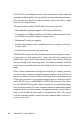
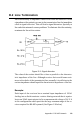
Figure D-6: Termination resistor locations
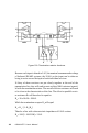
Because each input is biased to 2.4 V, the nominal common mode voltage
of balanced RS-485 systems, the 18 kΩ on the input can be taken as
being in series across the input of each individual receiver.
If thirty of these receivers are put closely together at the end of the
transmission line, they will tend to react as thirty 36kΩ resistors in paral-
lel with the termination resistor. The overall effective resistance will need
to be close to the characteristics of the line. The effective parallel receiv-
er resistance R
P
will therefore be equal to:
R
P
= 36 x 10
3
/30 = 1200 Ω
While the termination receptor R
T
will equal:
R
T
= R
O
/ [1 - R
O
/R
P
]
Thus for a line with a characteristic impedance of 100 Ω resistor
R
T
= 100/[1 - 100/1200] = 110 Ω