
User Manual


Appendix D RS-485 Network 59
D.2 Line Termination
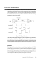
Each discontinuity in impedance causes reflections and distortion. When
a impedance discontinuity occurs in the transmission line the immediate
effect is signal reflection. This will lead to signal distortion. Specially at
line ends this mismatch causes problems. To eliminate this discontinuity,
terminate the line with a resistor.
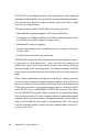
Figure D-5: Signal distortion
The value of the resistor should be a close as possible to the character-
istic impedance of the line. Although receiver devices add some resis-
tance to the whole of the transmission line, normally it is sufficient to the
resistor impedance should equal the characteristic impedance of the line.
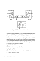
Example:
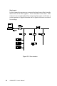
Each input of the receivers has a nominal input impedance of 18 kΩ
feeding into a diode transistor- resistor biasing network that is equiva-
lent to an 18 kΩ input resistor tied to a common mode voltage of 2.4 V. It
is this configuration which provides the large common range of the re-
ceiver required for RS-485 systems! (See Figure C-6 below).