
User Manual

ADAM-4541 User's Manual
Troubleshooting
Possible reasons for malfunction
Ø The TX and RX connections are reversed.
Solution: Make sure the fiber connection is made
so that the TX of one end is connected
to the RX of the other.
Ø Poor connection between the ADAM-4541 and the
communication port.
Solution: Make sure the ADAM-4541 is securely
plugged into the communication port.
Ø Attenuation on the fiber causes the signal level to
drop below the accepted level.
Solution: Reduce the attenuation by reducing
connector loss, transmission distances, etc.
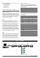
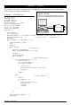
Ø The connection between the communication ports
is neither DTE to DTE nor DCE to DCE, but is a
DTE to DCE connection.
Solution: Add a converter to one of the optical
modems, so that the pin assignments
from the communication port to the
modem are from pin 2 to pin 3 and from
pin 3 to pin 2.
Ø The fiber has been damaged.
Solution: Repair or replace the fiber.
Ø The ADAM-4541 has been damaged.
Solution: Use the supplied software to perform a
loop-back test of the optical modem to
determine whether it has really been
damaged.
Power Supply
For the ease of use in industrial environments, the
ADAM modules are designed to accept industry
standard +24 V
DC
unregulated power. Operation is
guaranteed when using any power supply between
+10 and +30 V
DC
. Power ripples must be limited to 5 V
peak to peak, while the voltage in all cases must be
maintained between +10 and +30 V
DC
. All power
supply specifications are referenced at the module
connector.
The power cables should be selected according to the
number of modules connected and the length of the
power lines. When using a network with long cables,
we advise the use of thicker wire, to limit line voltage
drop. In addition to serious voltage drops, long voltage
lines can also cause interference with communication
wires.
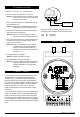
We advise that the following standard colors (as
indicated on the modules) be used for power lines:
+Vs è (R) Red
GND è (B) Black
Front View
-
+
Power supply
+10 ~ +30 V
(R) +Vs
10
(B) GND
-
+