
User's Manual
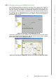
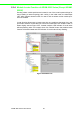
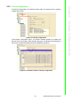
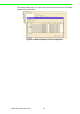

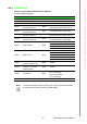
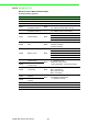
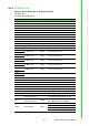
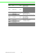
Table Of Contents
- ADAM-2000 Series
- 1 Understanding Your System
- 1.1 Introduction
- Figure 1.1 ADAM-2000 Series System Architecture
- Figure 1.2 ADAM-2000 Series Operating Distance
- 1.1.1 IEEE 802.15.4 Wireless Standard
- 1.1.2 Wireless Sensor Network
- 1.1.3 Low-power Consumption and Battery-Powered Design
- 1.1.4 Sensor Embedded Design
- 1.1.5 Wireless Signal Indicator
- 1.1.6 Industrial Standard Modbus Protocol
- 1.1.7 SCADA Software Support
- 1.1.8 Advantech Software Alignment
- 1.2 Specifications
- 1.3 Dimensions
- 1.4 Mounting
- 1.5 Wiring & Connections
- 1.1 Introduction
- 2 Selecting Your Hardware
- 3 Module Introduction
- 4 Installation Guide
- 5 Software Configuration Guide
- 5.1 System Software Configuration Utility
- 5.2 Installing AdamApax .NET Utility Software
- 5.3 AdamApax .NET Utility Operation
- Figure 5.1 AdamApax .NET Utility Operation Window
- Figure 5.2 AdamApax .NET Utility Toolbar
- 5.3.1 USB Driver Installation
- 5.3.2 Search and Configure the ADAM-2000 Series
- Figure 5.3 ADAM-2000 Series AdamApax .NET Utility Support
- Figure 5.4 Search the USB interface ADAM-2000 devices on the host PC for the virtual COM port.
- Figure 5.5 Search the COM port for the ADAM-2000 devices.
- Figure 5.6 Searching the network dialog
- Figure 5.7 Searching the ADAM-2000 coordinators.
- Figure 5.8 ADAM-2000 devices lists on the Tree View and Information page.
- Figure 5.9 The overview of ADAM-2000 end devices.
- Figure 5.10 The overview of ADAM-2000 routers
- 5.3.2.1 Gateway - ADAM-2520Z
- 5.3.2.2 Router - ADAM-2510Z
- 5.3.2.3 End Device - ADAM-2017PZ, ADAM-2031Z, ADAM-2051Z, ADAM-2051PZ
- 5.3.3 Network Topology of ADAM-2000 Series
- 5.3.4 Module Locate Function of ADAM-2000 Series (Except ADAM- 2520Z)
- 5.3.5 Group Configuration
- A ADAM-2000 Series Functions
- B Troubleshooting
- 1 Understanding Your System

67 ADAM-2000 Series User Manual
Appendix A ADAM-2000 Series Functions
A.2.1 ADAM-2520Z
Wireless Sensor Network Modbus RTU Gateway
03 Read Holding Registers
Table A.2: ADAM-2520Z Mapping Table
Address 4x Description Attribute Value
40211 Module Name 1 Read 0x2520
40212 Module Name 2 Read 0x5A00 (ASCII Code of 'Z')
40213
Wireless Module
Firmware Version 1
Read
Version Number
(ex: 0xA210 means version A2.10)
40214
Wireless Module
Firmware Version 2
Read
Build Version Number
(ex: 0x0003 means version B03)
40217
Kernel
Firmware Version 1
Read
Version Number
(ex: 0xA210 means version A2.10)
40218
Kernel
Firmware Version 2
Read
Build Version Number
(ex: 0x0500 means version B05)
40301 Module Status Read
Bit 0: 0; Initial Mode
Bit 0: 1; Normal Mode
Bit 1: 0; *No External Power Input
Bit 1: 1; External Power Input
40303 Battery Level Read
0x0000; Low
0x4000; Poor
0x8000; Normal
0xC000; Good
0xFFFF; Excellent
40304
Connection failed threshold
(N times of data cycle)
Read 0x0002
40305
Disconnection threshold
(N times of connection
failed threshold)
Read 0x0002
40306 Link Status Read
Bit 0: Connected
Bit 1: Link Failure
Bit 2: Disconnected
Bit 3: Connecting
40310 Device Short Address Read 0x0000~0xFFFF
Note! * It should be USB or battery power input. It does not recommend user
to use battery as power source for ADAM-2520Z.