
User's Manual
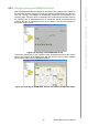
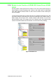
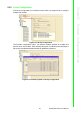
Table Of Contents
- ADAM-2000 Series
- 1 Understanding Your System
- 1.1 Introduction
- Figure 1.1 ADAM-2000 Series System Architecture
- Figure 1.2 ADAM-2000 Series Operating Distance
- 1.1.1 IEEE 802.15.4 Wireless Standard
- 1.1.2 Wireless Sensor Network
- 1.1.3 Low-power Consumption and Battery-Powered Design
- 1.1.4 Sensor Embedded Design
- 1.1.5 Wireless Signal Indicator
- 1.1.6 Industrial Standard Modbus Protocol
- 1.1.7 SCADA Software Support
- 1.1.8 Advantech Software Alignment
- 1.2 Specifications
- 1.3 Dimensions
- 1.4 Mounting
- 1.5 Wiring & Connections
- 1.1 Introduction
- 2 Selecting Your Hardware
- 3 Module Introduction
- 4 Installation Guide
- 5 Software Configuration Guide
- 5.1 System Software Configuration Utility
- 5.2 Installing AdamApax .NET Utility Software
- 5.3 AdamApax .NET Utility Operation
- Figure 5.1 AdamApax .NET Utility Operation Window
- Figure 5.2 AdamApax .NET Utility Toolbar
- 5.3.1 USB Driver Installation
- 5.3.2 Search and Configure the ADAM-2000 Series
- Figure 5.3 ADAM-2000 Series AdamApax .NET Utility Support
- Figure 5.4 Search the USB interface ADAM-2000 devices on the host PC for the virtual COM port.
- Figure 5.5 Search the COM port for the ADAM-2000 devices.
- Figure 5.6 Searching the network dialog
- Figure 5.7 Searching the ADAM-2000 coordinators.
- Figure 5.8 ADAM-2000 devices lists on the Tree View and Information page.
- Figure 5.9 The overview of ADAM-2000 end devices.
- Figure 5.10 The overview of ADAM-2000 routers
- 5.3.2.1 Gateway - ADAM-2520Z
- 5.3.2.2 Router - ADAM-2510Z
- 5.3.2.3 End Device - ADAM-2017PZ, ADAM-2031Z, ADAM-2051Z, ADAM-2051PZ
- 5.3.3 Network Topology of ADAM-2000 Series
- 5.3.4 Module Locate Function of ADAM-2000 Series (Except ADAM- 2520Z)
- 5.3.5 Group Configuration
- A ADAM-2000 Series Functions
- B Troubleshooting
- 1 Understanding Your System

61 ADAM-2000 Series User Manual
Chapter 5 Software Configuration Guide
5.3.3 Network Topology of ADAM-2000 Series
After the ADAM-2000 devices have been discovered, all the devices will be listed on
the Tree View and the Topology also lists the relations between devices in advance.
Click the Topology, the relations of ADAM-2000 devices will be illustrated in the
Topology page. There are three components with model name and status listed on
the Topology. The "C" represents the role of Coordinator, the "R" represents the role
of Router and the "E" represents the role of End Device. You can scroll position on
the screen using a mouse.
Figure 5.20 Topology of the ADAM-2000 series
The function allows user to put a picture on the background and drag the compo-
nents to any positions of the background. With the function, user can easily maintain
and check the status of the ADAM-2000 network.
Figure 5.21 Topology of ADAM-2000 network with specific background image