
User's Manual
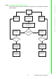
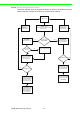
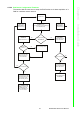
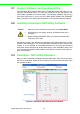
Table Of Contents
- ADAM-2000 Series
- 1 Understanding Your System
- 1.1 Introduction
- Figure 1.1 ADAM-2000 Series System Architecture
- Figure 1.2 ADAM-2000 Series Operating Distance
- 1.1.1 IEEE 802.15.4 Wireless Standard
- 1.1.2 Wireless Sensor Network
- 1.1.3 Low-power Consumption and Battery-Powered Design
- 1.1.4 Sensor Embedded Design
- 1.1.5 Wireless Signal Indicator
- 1.1.6 Industrial Standard Modbus Protocol
- 1.1.7 SCADA Software Support
- 1.1.8 Advantech Software Alignment
- 1.2 Specifications
- 1.3 Dimensions
- 1.4 Mounting
- 1.5 Wiring & Connections
- 1.1 Introduction
- 2 Selecting Your Hardware
- 3 Module Introduction
- 4 Installation Guide
- 5 Software Configuration Guide
- 5.1 System Software Configuration Utility
- 5.2 Installing AdamApax .NET Utility Software
- 5.3 AdamApax .NET Utility Operation
- Figure 5.1 AdamApax .NET Utility Operation Window
- Figure 5.2 AdamApax .NET Utility Toolbar
- 5.3.1 USB Driver Installation
- 5.3.2 Search and Configure the ADAM-2000 Series
- Figure 5.3 ADAM-2000 Series AdamApax .NET Utility Support
- Figure 5.4 Search the USB interface ADAM-2000 devices on the host PC for the virtual COM port.
- Figure 5.5 Search the COM port for the ADAM-2000 devices.
- Figure 5.6 Searching the network dialog
- Figure 5.7 Searching the ADAM-2000 coordinators.
- Figure 5.8 ADAM-2000 devices lists on the Tree View and Information page.
- Figure 5.9 The overview of ADAM-2000 end devices.
- Figure 5.10 The overview of ADAM-2000 routers
- 5.3.2.1 Gateway - ADAM-2520Z
- 5.3.2.2 Router - ADAM-2510Z
- 5.3.2.3 End Device - ADAM-2017PZ, ADAM-2031Z, ADAM-2051Z, ADAM-2051PZ
- 5.3.3 Network Topology of ADAM-2000 Series
- 5.3.4 Module Locate Function of ADAM-2000 Series (Except ADAM- 2520Z)
- 5.3.5 Group Configuration
- A ADAM-2000 Series Functions
- B Troubleshooting
- 1 Understanding Your System

ADAM-2000 Series User Manual 46
4.4 Conduct a Site Survey
Performing a Site Survey before installing the WSN is a necessary procedure to
ensure reliable communication. The following description demonstrates the standard
process of Site Survey.
4.4.1 Before Going Onsite
1. Ask the customer for the maps and collect the information in previous chapter
the more the merrier.
2. Check with the customer for the possible position to install the coordinator.
3. Setup all modules
Prepare the following items:
– ADAM-2520Z *1
– ADAM-2510Z *8, it depends on the area of site, 8 router can organize two 5-
hop network
– ADAM-2051PZ *1
– 2 AA batteries for the above modules
Set all modules in same PAN ID and RF Channel. The RF Channel suggests to
be set to channel 15 or 20 to avoid the interference of WLAN.
Set all modules' data cycle to 5 second.
Set all modules as individual ID address.
Install batteries for all modules.
Switch all modules to normal mode and use utility to check all modules are
work.
Switch all modules to initial mode and remove the batteries.
4.4.2 Onsite Survey
1. Setup Coordinator
When arriving the site, power up ADAM-2520Z with batteries and switch it to
normal mode.
Install ADAM-2520Z at the place that can be seen from most of the place or cor-
ner to ensure the signal can be easier to be accessed.
If possible, do not install on the concrete wall, heavy column, or girder.
The antenna should be vertical to the plane that going to install other modules.
2. Add Router
Install batteries to one of the ADAM-2051PZ, and switch it to normal mode.
Press the button of ADAM-2051PZ one time to check the link quality
Walk away from coordinator and keep checking the LQI until only one LED level
is on.
Add one router with batteries and work in normal mode at that position
Check the LQI of router 5 times to make sure a least one LED level is on.
Check the ADAM-2051PZ has full LED level at the same place, if only one LED
level is on, switch it to initial mode and then back to normal mode to re-register
the routing.
Walk away from the new added router and use the same way to add next router
until the position of end-devices that will install can access the network.