
User's Manual
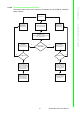
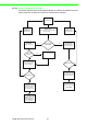
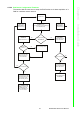
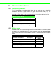
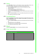
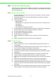
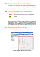
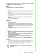
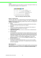
Table Of Contents
- ADAM-2000 Series
- 1 Understanding Your System
- 1.1 Introduction
- Figure 1.1 ADAM-2000 Series System Architecture
- Figure 1.2 ADAM-2000 Series Operating Distance
- 1.1.1 IEEE 802.15.4 Wireless Standard
- 1.1.2 Wireless Sensor Network
- 1.1.3 Low-power Consumption and Battery-Powered Design
- 1.1.4 Sensor Embedded Design
- 1.1.5 Wireless Signal Indicator
- 1.1.6 Industrial Standard Modbus Protocol
- 1.1.7 SCADA Software Support
- 1.1.8 Advantech Software Alignment
- 1.2 Specifications
- 1.3 Dimensions
- 1.4 Mounting
- 1.5 Wiring & Connections
- 1.1 Introduction
- 2 Selecting Your Hardware
- 3 Module Introduction
- 4 Installation Guide
- 5 Software Configuration Guide
- 5.1 System Software Configuration Utility
- 5.2 Installing AdamApax .NET Utility Software
- 5.3 AdamApax .NET Utility Operation
- Figure 5.1 AdamApax .NET Utility Operation Window
- Figure 5.2 AdamApax .NET Utility Toolbar
- 5.3.1 USB Driver Installation
- 5.3.2 Search and Configure the ADAM-2000 Series
- Figure 5.3 ADAM-2000 Series AdamApax .NET Utility Support
- Figure 5.4 Search the USB interface ADAM-2000 devices on the host PC for the virtual COM port.
- Figure 5.5 Search the COM port for the ADAM-2000 devices.
- Figure 5.6 Searching the network dialog
- Figure 5.7 Searching the ADAM-2000 coordinators.
- Figure 5.8 ADAM-2000 devices lists on the Tree View and Information page.
- Figure 5.9 The overview of ADAM-2000 end devices.
- Figure 5.10 The overview of ADAM-2000 routers
- 5.3.2.1 Gateway - ADAM-2520Z
- 5.3.2.2 Router - ADAM-2510Z
- 5.3.2.3 End Device - ADAM-2017PZ, ADAM-2031Z, ADAM-2051Z, ADAM-2051PZ
- 5.3.3 Network Topology of ADAM-2000 Series
- 5.3.4 Module Locate Function of ADAM-2000 Series (Except ADAM- 2520Z)
- 5.3.5 Group Configuration
- A ADAM-2000 Series Functions
- B Troubleshooting
- 1 Understanding Your System

45 ADAM-2000 Series User Manual
Chapter 4 Installation Guide
4.3.3 Pairing
In the Initial Mode, Routers and End Devices must be associated with the corre-
sponding Coordinator. The function is for Router and End Devices only.
1. Press the Function Button 5 times to enter the change Pair ID mode.
2. Status LED blinks
3. Level Index LED turns on to indicate Pair ID.
4. Press the Function Button once to change Pair ID.
5. Press and hold the Function Button for over 2 seconds to save and confirm the
Pair ID.
6. Press the Function Button 3 times to associate with specific Pair ID Coordina-
tor.
7. Error LED turns off when it join a PAN.
4.3.4 Associating Devices
Routers and End Devices must have to associate with corresponding Pair ID Coordi-
nator in Initial Mode to build up the wireless communication. The function is for
Router and End Devices only.
1. Press the Function Button 3 times to join a PAN with specific Pair ID Coordina-
tor.
2. Status LED turns on, Error LED blinks.
3. Level LED turns on to indicate the Pair ID to associate with.
4. Error LED turns off when it joins a PAN.
4.3.5 Reboot
Press the Function Button for over 3 seconds to reboot the device.
4.3.6 Button Function Table
Table 4.3: Button Functions
Press Button Function
2 Seconds Confirm the Pair ID
3 Seconds Reboot
Once Link Quality Indicator
2 Times Battery Level
3 Times Network Association
5 Times Pair ID Selection