
User's Manual
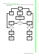
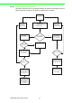
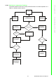
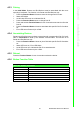
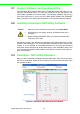
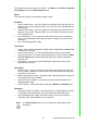
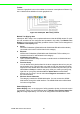
Table Of Contents
- ADAM-2000 Series
- 1 Understanding Your System
- 1.1 Introduction
- Figure 1.1 ADAM-2000 Series System Architecture
- Figure 1.2 ADAM-2000 Series Operating Distance
- 1.1.1 IEEE 802.15.4 Wireless Standard
- 1.1.2 Wireless Sensor Network
- 1.1.3 Low-power Consumption and Battery-Powered Design
- 1.1.4 Sensor Embedded Design
- 1.1.5 Wireless Signal Indicator
- 1.1.6 Industrial Standard Modbus Protocol
- 1.1.7 SCADA Software Support
- 1.1.8 Advantech Software Alignment
- 1.2 Specifications
- 1.3 Dimensions
- 1.4 Mounting
- 1.5 Wiring & Connections
- 1.1 Introduction
- 2 Selecting Your Hardware
- 3 Module Introduction
- 4 Installation Guide
- 5 Software Configuration Guide
- 5.1 System Software Configuration Utility
- 5.2 Installing AdamApax .NET Utility Software
- 5.3 AdamApax .NET Utility Operation
- Figure 5.1 AdamApax .NET Utility Operation Window
- Figure 5.2 AdamApax .NET Utility Toolbar
- 5.3.1 USB Driver Installation
- 5.3.2 Search and Configure the ADAM-2000 Series
- Figure 5.3 ADAM-2000 Series AdamApax .NET Utility Support
- Figure 5.4 Search the USB interface ADAM-2000 devices on the host PC for the virtual COM port.
- Figure 5.5 Search the COM port for the ADAM-2000 devices.
- Figure 5.6 Searching the network dialog
- Figure 5.7 Searching the ADAM-2000 coordinators.
- Figure 5.8 ADAM-2000 devices lists on the Tree View and Information page.
- Figure 5.9 The overview of ADAM-2000 end devices.
- Figure 5.10 The overview of ADAM-2000 routers
- 5.3.2.1 Gateway - ADAM-2520Z
- 5.3.2.2 Router - ADAM-2510Z
- 5.3.2.3 End Device - ADAM-2017PZ, ADAM-2031Z, ADAM-2051Z, ADAM-2051PZ
- 5.3.3 Network Topology of ADAM-2000 Series
- 5.3.4 Module Locate Function of ADAM-2000 Series (Except ADAM- 2520Z)
- 5.3.5 Group Configuration
- A ADAM-2000 Series Functions
- B Troubleshooting
- 1 Understanding Your System

ADAM-2000 Series User Manual 42
4.2.2.3 Router Configuration Flowchart
The section tells the user how to setup the Router to enhance the wireless communi-
cation range and coverage of a PAN for a wireless sensor network.
Install Power
Press Function Button 3
times to join the PAN.
Amber LED turns on.
Error LED blinks.
Please refer to
Appendix B for
troubleshooting.
Please refer to
Appendix B for
troubleshooting.
All LEDs turn On
(Green LED turns on while powering by
external power)
Configured ready for
Normal Mode
Initial Mode:
Status LED turns on
Normal Mode:
Status LED turns off,
Error LED blinks.
Error LED turns off
Successfully join a PAN
with default PAN ID and
RF channel. Amber
LED indicating Pair ID.
Successfully join a PAN
with user defined PAN
ID and RF channel.
Open AdamApax .NET
Utility to configure the
ADAM-2000 series,
refer to Chapter 5 for
more information.
Repeat and pass data/
signal from end nodes
to coordinator.
Error LED turns off
Join PAN with
Pair ID 1
Press Function Button 5
times to change Pair ID.
No Yes
No
No
No
Yes
Yes
Yes