
User's Manual
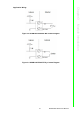

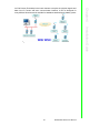
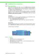
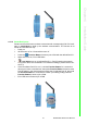
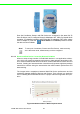
Table Of Contents
- ADAM-2000 Series
- 1 Understanding Your System
- 1.1 Introduction
- Figure 1.1 ADAM-2000 Series System Architecture
- Figure 1.2 ADAM-2000 Series Operating Distance
- 1.1.1 IEEE 802.15.4 Wireless Standard
- 1.1.2 Wireless Sensor Network
- 1.1.3 Low-power Consumption and Battery-Powered Design
- 1.1.4 Sensor Embedded Design
- 1.1.5 Wireless Signal Indicator
- 1.1.6 Industrial Standard Modbus Protocol
- 1.1.7 SCADA Software Support
- 1.1.8 Advantech Software Alignment
- 1.2 Specifications
- 1.3 Dimensions
- 1.4 Mounting
- 1.5 Wiring & Connections
- 1.1 Introduction
- 2 Selecting Your Hardware
- 3 Module Introduction
- 4 Installation Guide
- 5 Software Configuration Guide
- 5.1 System Software Configuration Utility
- 5.2 Installing AdamApax .NET Utility Software
- 5.3 AdamApax .NET Utility Operation
- Figure 5.1 AdamApax .NET Utility Operation Window
- Figure 5.2 AdamApax .NET Utility Toolbar
- 5.3.1 USB Driver Installation
- 5.3.2 Search and Configure the ADAM-2000 Series
- Figure 5.3 ADAM-2000 Series AdamApax .NET Utility Support
- Figure 5.4 Search the USB interface ADAM-2000 devices on the host PC for the virtual COM port.
- Figure 5.5 Search the COM port for the ADAM-2000 devices.
- Figure 5.6 Searching the network dialog
- Figure 5.7 Searching the ADAM-2000 coordinators.
- Figure 5.8 ADAM-2000 devices lists on the Tree View and Information page.
- Figure 5.9 The overview of ADAM-2000 end devices.
- Figure 5.10 The overview of ADAM-2000 routers
- 5.3.2.1 Gateway - ADAM-2520Z
- 5.3.2.2 Router - ADAM-2510Z
- 5.3.2.3 End Device - ADAM-2017PZ, ADAM-2031Z, ADAM-2051Z, ADAM-2051PZ
- 5.3.3 Network Topology of ADAM-2000 Series
- 5.3.4 Module Locate Function of ADAM-2000 Series (Except ADAM- 2520Z)
- 5.3.5 Group Configuration
- A ADAM-2000 Series Functions
- B Troubleshooting
- 1 Understanding Your System

ADAM-2000 Series User Manual 36
4.2 Establish the Connection
4.2.1 Basic Installation
In the side of the ADAM-2000 series, users can find Mode Switch and Function
Button. The two hardware keys contain several combinations for device operations.
The default position of Mode Switch is set in the Initial Mode to configure the device
and establish connection for Normal Mode.
It is easily to use the ADAM-2000 series with default configuration. Push the Mode
Switch on the side of ADAM-2000 devices to Normal position then the PAN can be
operated to collect data from modules. The ADAM-2000 series also provides
advanced functions for further operations.
Initial Mode
The Initial Mode is for user to configure parameters of the ADAM-2000 devices.
While the device is in the Initial Mode, Status LED turns on.
1. Push the Mode Switch to the Initial position.
2. Open the AdamApax .NET Utility to search and configure the ADAM-2000
devices.
Normal Mode
After all the ADAM-2000 devices are configured in the same PAN ID and RF channel,
push the Mode Switch to Normal position to perform the Wireless Sensor Network.
Connection Steps in Initial Mode:
4.2.1.1 Coordinator
1. Power on.
2. All LEDs turn on for 0.5 second then turn off.
3. Status LED turns on, Error LED blinks.
4. Level Index turns on to indicate Pair ID 1. (Pair ID will automatically count if
there is a coordinator nearby.
5. Error LED turns off when it hosts a PAN.