
User's Manual
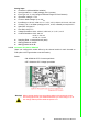
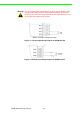
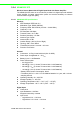
Table Of Contents
- ADAM-2000 Series
- 1 Understanding Your System
- 1.1 Introduction
- Figure 1.1 ADAM-2000 Series System Architecture
- Figure 1.2 ADAM-2000 Series Operating Distance
- 1.1.1 IEEE 802.15.4 Wireless Standard
- 1.1.2 Wireless Sensor Network
- 1.1.3 Low-power Consumption and Battery-Powered Design
- 1.1.4 Sensor Embedded Design
- 1.1.5 Wireless Signal Indicator
- 1.1.6 Industrial Standard Modbus Protocol
- 1.1.7 SCADA Software Support
- 1.1.8 Advantech Software Alignment
- 1.2 Specifications
- 1.3 Dimensions
- 1.4 Mounting
- 1.5 Wiring & Connections
- 1.1 Introduction
- 2 Selecting Your Hardware
- 3 Module Introduction
- 4 Installation Guide
- 5 Software Configuration Guide
- 5.1 System Software Configuration Utility
- 5.2 Installing AdamApax .NET Utility Software
- 5.3 AdamApax .NET Utility Operation
- Figure 5.1 AdamApax .NET Utility Operation Window
- Figure 5.2 AdamApax .NET Utility Toolbar
- 5.3.1 USB Driver Installation
- 5.3.2 Search and Configure the ADAM-2000 Series
- Figure 5.3 ADAM-2000 Series AdamApax .NET Utility Support
- Figure 5.4 Search the USB interface ADAM-2000 devices on the host PC for the virtual COM port.
- Figure 5.5 Search the COM port for the ADAM-2000 devices.
- Figure 5.6 Searching the network dialog
- Figure 5.7 Searching the ADAM-2000 coordinators.
- Figure 5.8 ADAM-2000 devices lists on the Tree View and Information page.
- Figure 5.9 The overview of ADAM-2000 end devices.
- Figure 5.10 The overview of ADAM-2000 routers
- 5.3.2.1 Gateway - ADAM-2520Z
- 5.3.2.2 Router - ADAM-2510Z
- 5.3.2.3 End Device - ADAM-2017PZ, ADAM-2031Z, ADAM-2051Z, ADAM-2051PZ
- 5.3.3 Network Topology of ADAM-2000 Series
- 5.3.4 Module Locate Function of ADAM-2000 Series (Except ADAM- 2520Z)
- 5.3.5 Group Configuration
- A ADAM-2000 Series Functions
- B Troubleshooting
- 1 Understanding Your System

ADAM-2000 Series User Manual 26
Built-in 120 Ohm Resister (Current)
Figure 3.1 Current Input Wiring Diagram of ADAM-2017PZ
Figure 3.2 Voltage Input Wiring Diagram of ADAM-2017PZ
Warning! Incorrect analog input configuration may cause device damage. After
change analog input switch of channel please change correct input
range for each channel through AdamApax .NET utility before you con-
nect analog input signal to the module.