
User's Manual

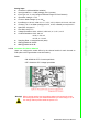
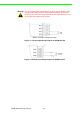

Table Of Contents
- ADAM-2000 Series
- 1 Understanding Your System
- 1.1 Introduction
- Figure 1.1 ADAM-2000 Series System Architecture
- Figure 1.2 ADAM-2000 Series Operating Distance
- 1.1.1 IEEE 802.15.4 Wireless Standard
- 1.1.2 Wireless Sensor Network
- 1.1.3 Low-power Consumption and Battery-Powered Design
- 1.1.4 Sensor Embedded Design
- 1.1.5 Wireless Signal Indicator
- 1.1.6 Industrial Standard Modbus Protocol
- 1.1.7 SCADA Software Support
- 1.1.8 Advantech Software Alignment
- 1.2 Specifications
- 1.3 Dimensions
- 1.4 Mounting
- 1.5 Wiring & Connections
- 1.1 Introduction
- 2 Selecting Your Hardware
- 3 Module Introduction
- 4 Installation Guide
- 5 Software Configuration Guide
- 5.1 System Software Configuration Utility
- 5.2 Installing AdamApax .NET Utility Software
- 5.3 AdamApax .NET Utility Operation
- Figure 5.1 AdamApax .NET Utility Operation Window
- Figure 5.2 AdamApax .NET Utility Toolbar
- 5.3.1 USB Driver Installation
- 5.3.2 Search and Configure the ADAM-2000 Series
- Figure 5.3 ADAM-2000 Series AdamApax .NET Utility Support
- Figure 5.4 Search the USB interface ADAM-2000 devices on the host PC for the virtual COM port.
- Figure 5.5 Search the COM port for the ADAM-2000 devices.
- Figure 5.6 Searching the network dialog
- Figure 5.7 Searching the ADAM-2000 coordinators.
- Figure 5.8 ADAM-2000 devices lists on the Tree View and Information page.
- Figure 5.9 The overview of ADAM-2000 end devices.
- Figure 5.10 The overview of ADAM-2000 routers
- 5.3.2.1 Gateway - ADAM-2520Z
- 5.3.2.2 Router - ADAM-2510Z
- 5.3.2.3 End Device - ADAM-2017PZ, ADAM-2031Z, ADAM-2051Z, ADAM-2051PZ
- 5.3.3 Network Topology of ADAM-2000 Series
- 5.3.4 Module Locate Function of ADAM-2000 Series (Except ADAM- 2520Z)
- 5.3.5 Group Configuration
- A ADAM-2000 Series Functions
- B Troubleshooting
- 1 Understanding Your System

25 ADAM-2000 Series User Manual
Chapter 3 Module Introduction
Analog Input
Channels: 6 (differential/Non-Isolation)
Input Impedance: > 10 MΩ (voltage) 120 Ω (current)
lnput Type: mV, V, mA (Configure Different Range for Each Channel)
Input Max: Voltage: +/-15V
Common Mode Voltage: Up to 10V
DC
lnput Range: ±150 mV, ±500 mV, ±1 V, ±5 V, ±10 V, ±20 mA, 0-20 mA, 4-20 mA
Accuracy: ±0.1% or Better (voltage) at 25°C, ±0.2% or Better (current) at 25°C
Span Drift: ±30 ppm/°C
Zero Drift: ±22 μV/°C
Voltage Resolution:16 bit; ±150 mV, ±500 mV, ±1 V, ±5 V, ±10 V
Current Resolution:15 bit; ±20 mA
14 bit; 0 ~ 20 mA
13.5 bit; 4 ~ 20 mA
Sampling Rate: 12 sample/second (total)
CMR @ 50/60 Hz 100 dB
NMR @ 50/60 Hz 65 dB
3.2.1.2 Connector Pin Define & Switch
Users can configure the switch define by the channel switch for each channel on
PCB (refer to the Figure below to see its location):
Switch:
ON: ADAM-2017PZ: Current Input Mode
OFF: ADAM-2017PZ: Voltage Input Mode
Warning! When change analog input type please always disconnect the power
and analog input from your module whenever you are working on it, do
not change switch position while the power is on.