
User's Manual

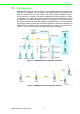
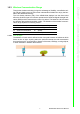
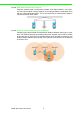
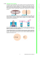
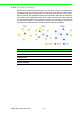
Table Of Contents
- ADAM-2000 Series
- 1 Understanding Your System
- 1.1 Introduction
- Figure 1.1 ADAM-2000 Series System Architecture
- Figure 1.2 ADAM-2000 Series Operating Distance
- 1.1.1 IEEE 802.15.4 Wireless Standard
- 1.1.2 Wireless Sensor Network
- 1.1.3 Low-power Consumption and Battery-Powered Design
- 1.1.4 Sensor Embedded Design
- 1.1.5 Wireless Signal Indicator
- 1.1.6 Industrial Standard Modbus Protocol
- 1.1.7 SCADA Software Support
- 1.1.8 Advantech Software Alignment
- 1.2 Specifications
- 1.3 Dimensions
- 1.4 Mounting
- 1.5 Wiring & Connections
- 1.1 Introduction
- 2 Selecting Your Hardware
- 3 Module Introduction
- 4 Installation Guide
- 5 Software Configuration Guide
- 5.1 System Software Configuration Utility
- 5.2 Installing AdamApax .NET Utility Software
- 5.3 AdamApax .NET Utility Operation
- Figure 5.1 AdamApax .NET Utility Operation Window
- Figure 5.2 AdamApax .NET Utility Toolbar
- 5.3.1 USB Driver Installation
- 5.3.2 Search and Configure the ADAM-2000 Series
- Figure 5.3 ADAM-2000 Series AdamApax .NET Utility Support
- Figure 5.4 Search the USB interface ADAM-2000 devices on the host PC for the virtual COM port.
- Figure 5.5 Search the COM port for the ADAM-2000 devices.
- Figure 5.6 Searching the network dialog
- Figure 5.7 Searching the ADAM-2000 coordinators.
- Figure 5.8 ADAM-2000 devices lists on the Tree View and Information page.
- Figure 5.9 The overview of ADAM-2000 end devices.
- Figure 5.10 The overview of ADAM-2000 routers
- 5.3.2.1 Gateway - ADAM-2520Z
- 5.3.2.2 Router - ADAM-2510Z
- 5.3.2.3 End Device - ADAM-2017PZ, ADAM-2031Z, ADAM-2051Z, ADAM-2051PZ
- 5.3.3 Network Topology of ADAM-2000 Series
- 5.3.4 Module Locate Function of ADAM-2000 Series (Except ADAM- 2520Z)
- 5.3.5 Group Configuration
- A ADAM-2000 Series Functions
- B Troubleshooting
- 1 Understanding Your System

9 ADAM-2000 Series User Manual
Chapter 1 Understanding Your System
1.2.3.4 ADAM-2000 Antenna Pattern
The antenna of the modules with power amplifier uses the Omni-directional antenna.
Its antenna pattern looks like a doughnut as the figure on the left below. The cross-
sectional view of the antenna pattern is on the right below. The plane vertical to
antenna has stronger signal, but the region on or under the antenna has lower signal.
The modules including: ADAM-2520Z, ADAM-2510Z, ADAM-2017PZ, and ADAM-
2051PZ.
The modules without power amplifier use a build-in antenna inside the module. The
build-in antenna is shown as a white bar on the left figure below. Its antenna pattern
is also looks like a doughnut which vertical to antenna. The modules including:
ADAM-2031Z and ADAM-2051Z.
For improving better performance of signal, user may need to adjust the angle of the
antenna to change the antenna pattern. Beware of the relationship of the angle
between position of router and end-devices.
The transmission distance of the modules is defined under the condition of clear line
of sight. Following are the top view of antenna. The modules with power amplifier has
less than 1000 m distance as the figure on the left, and the modules without power
amplifier are less than 110 m.