
User manual

USB-4751/4751L User Manual 14
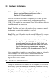
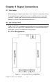
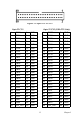
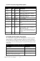
3.2.2 I/O Connector Signal Description
3.2.3 LED Indicator Status Description
The USB Module is equipped with a LED indicator to show the current
status of the device. When you plug the USB device into the USB port,
the LED indicator will blink five times and then stay lit to indicate that it
is on. Please refer to the following table for detailed LED indicator status
information.
Table 3.1: I/O Connector Signal Description
Signal Ref. Direction Description
PA<0~7,
10~17>
GND Input/Out-
put
Digital input/ output port A, channel
0~7 & channel 10~17.
PB<0~7,
10~17>
GND Input/Out-
put
Digital input/ output port B, channel
0~7 & channel 10~17.
PC<0~7,
10~17>
GND Input/Out-
put
Digital input/ output port C, channel
0~7 & channel 10~17.
+5V_OUT GND Output +5V DC power
C<1,2>_Out GND Output Output pins of counter/ timer 1 and 2
C<1,2>_Gate GND Input Gate control pins of counter/ timer 1
and 2
C<1,2>_In GND Input External clock source of counter/ timer
1 and 2
INT_Out GND Output Interrupt output. This pin changes to
logic 1 whenever the
USB-4751 generates an interrupt, and
returns to logic 0 when the interrupt is
cleared.
GND - - Digital ground
Table 3.2: LED Indicator Status Description
LED Status Description
On Device ready for work
Off Device not ready to work
Slow Blinking (5 times) Device initialization
Fast Blinking
(Depends on data transfer speed).
Device working