Enterprise120TM – Operation Manual Issue 2 ENTERPRISE120 UK Office Phone +44 1480 357 600 Fax +44 1480 357 601 US Office Phone +1 480 839 4136 Fax +1 480 839 0860 Canada Office Phone +1 514 420 0045 Fax +1 514 420 0073 E-mail Sales.UK@AdvantechWireless.com Website: www.AdvantechWireless.
TABLE OF CONTENTS 1. Overview – Technical Description 3 2. Installation and Set-up 3 3. i-Point ACU Controller Installation 4 4. Maintenance 6 5. Spares and Replacement Parts 6 6. Manual Over Ride 7 7. Overall Dimensions 8 8. Mounting Bracket Positions 9 ENTERPRISE120 UK Office Phone +44 1480 357 600 Fax +44 1480 357 601 US Office Phone +1 480 839 4136 Fax +1 480 839 0860 Canada Office Phone +1 514 420 0045 Fax +1 514 420 0073 E-mail Sales.UK@AdvantechWireless.
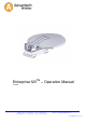
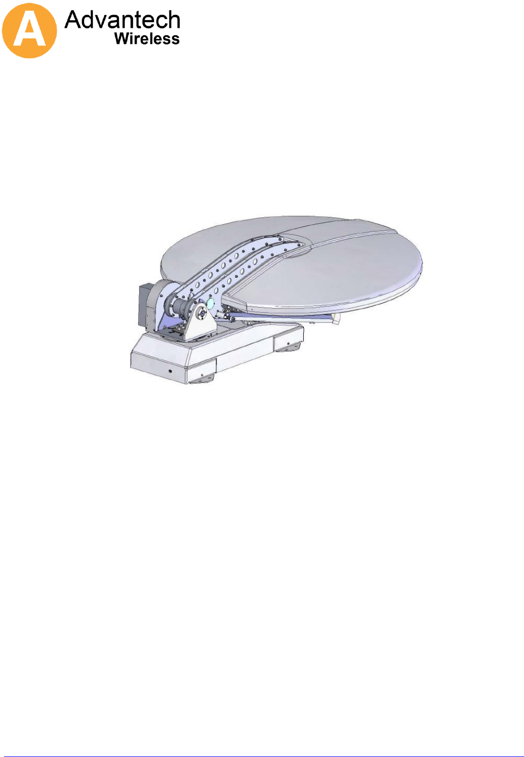
1. Overview – Technical Description The ENTERPRISE120 is an azimuth over elevation positioning mount with motorised polarisation control. All axis feature simple and very robust 24V DC motor drives giving reliable, low backlash, high and low speed motion controlled by either a jog controller or a fully auto-pointing controller. The optical layout is a dual offset Gregorian antenna which naturally produces cross polarisation patterns which easily meet the 29-25 log theta requirement.
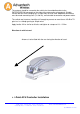
The antenna should be secured to the vehicle via the welded brackets to the ENTERPRISE120 framework on the sides of the antenna base framework. Suitable vehicle roof bars with clamping nuts (U-Bolts M6) must be used. Additional connections must be made connecting coax (Tx and Rx), control cable to controller and power cables. The vehicle roof structure should be stiff enough to prevent no more than a 0.5 dB of TX gain loss in a 30mph gusting to 45mph wind.
Install controller into electronics rack and attach control cable ensuring it is securely and fully pushed into its connector. (see Addendum 1) User Interface Unit (UIU) The antenna controller may be operated directly from the front panel of the User Interface Unit (UIU), a hand held controller or via a remote control link. A Graphical User Interface (GUI) program is provided.
Note that if the UIU is to be used for selecting the Reference and Target satellites, then those satellites must appear in the first 10 slots of satellite data Ensure that the reference and target satellites are as required and that the final Pol and final LNB settings match the settings required to access the satellite after acquisition. Command Deploy (from the UIU or GUI).
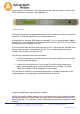
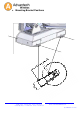
6. Manual Over Ride Azimuth Insert hexagon key Elevation Ensure that the DC power to the unit is switched off, remove the 4 cover screws indicated, remove the cover then insert hexagon key into the shaft end. ENTERPRISE120 UK Office Phone +44 1480 357 600 Fax +44 1480 357 601 US Office Phone +1 480 839 4136 Fax +1 480 839 0860 Canada Office Phone +1 514 420 0045 Fax +1 514 420 0073 E-mail Sales.UK@AdvantechWireless.com Website: www.AdvantechWireless.
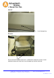
7. ENTERPRISE120 Overall Dimensions UK Office Phone +44 1480 357 600 Fax +44 1480 357 601 US Office Phone +1 480 839 4136 Fax +1 480 839 0860 Canada Office Phone +1 514 420 0045 Fax +1 514 420 0073 E-mail Sales.UK@AdvantechWireless.com Website: www.AdvantechWireless.
8. Mounting Bracket Positions ENTERPRISE120 UK Office Phone +44 1480 357 600 Fax +44 1480 357 601 US Office Phone +1 480 839 4136 Fax +1 480 839 0860 Canada Office Phone +1 514 420 0045 Fax +1 514 420 0073 E-mail Sales.UK@AdvantechWireless.com Website: www.AdvantechWireless.
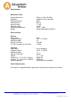
Specification:- Mechanical Data Overall dimensions : Geometry : Reflector material : Feed interface : Azimuth range : Elevation range : Operating temperature : Weight 1.66m x 1.25m x 0.450m Gregorian offset, dual optic SMC WR 75 +/- 185° 10~90° -30°C ~ +60°C 95 kg (Depending on options) Electrical Data Receive Polarisation : Frequency band : 3dB beam width : Gain @ 12,5 GHz : G/T (30° elevation) @ 12.
Addendum 1 i-Point Operation Monitoring The i-Point Antenna control system is designed to be very simple to operate and is expected to be fully automatic in acquiring the required satellite signals. However the system does not provide very much user feedback if the satellite acquisition operation does not complete. This document is intended to provide method to gather information on the progress of the satellite acquisition.
D Connector Signal RJ-11 Connector Pin 5 Ground Pin 1 Pin 3 Term Data OUT Pin 2 Pin 2 Term Data IN Pin 3 Pin 6 Not Used Pin 4 Pin 1 Common Pin 5 Do Not Connect + 5VDC @ 100 mA Pin 6 This diagram shows the pin order when viewed from plug cable entry. 2 Normal Operation The i-Point's normal "deploy" operation is made up of several stages. There is information provided at some stages which can be helpful to diagnose a system having problems. First start to capture the information on the serial port.
To check the magnetometer heading information type "platform". The third number is the heading angle in degrees. This number could be as much as +/- 20 degrees from the correct reading without stopping the system working. If the error is greater than 20 degrees then this can cause problems. If required the correct heading can be provided. Type the command "platform 0 0 zz" where zz is the correct heading in degrees. 2.3 Satellite Sweep The start of the satellite sweep is shown in the diagnostic data.
should be more than half of the number of channels checked. Again if the system peaks up on the wrong satellite, but it is recognised as such then the system will attempt to got to the target satellite again. If the satellite is recognised then the system will re-calculate the platform heading. 2.9 Set polarisation to final position. At this stage the Feed is moved to the final Pol position. 3 GUI Program The ipoint.