
User Manual

Trilogue-1NM
User Manual V1.4
Advanced RF Technologies, Inc. Proprietary Document Page 43 of 43
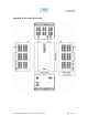
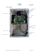
Power Supply
It provides DC power to each module within the repeater.
Controller
It is responsible for monitoring the status of each module and controls the
parameters.
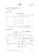
Down Converter Module
The downlink RF signal that enters through the cavity filter is converted to IF
frequency, which is later converted back to RF frequency through SAW filtering.
Up Converter Module
The uplink RF signal that enters through the cavity filter is converted to IF
frequency, which is later converted back to RF frequency through SAW filtering.
Duplexer
It consists of two BPFs (band-pass filters): PCS TX (1930 ~ 1995 MHz) & RX
(1850 ~ 1915 MHz)
HPA
It receives the output signal from the Up/Down converter module and amplifies
the signal to the repeater’s rated maximum power level.
Modem Box Adapter
Adapter for modem box