PSR78 Public Safety Repeater USER MANUAL Version 0.1 3116 Vanowen St. Burbank, CA 91505 Tel: 818-840-8131 Fax: 818-840-8138 www.adrftech.
PSR78 Repeater User Manual V0.1 Glossary The following is a list of abbreviations and terms used throughout this document.
PSR78 Repeater User Manual V0.1 Released version: 0.1 Information in this document is subject to change without notice. Advanced RF Technologies, Inc. 1996-2011. All rights reserved. Please send comments to: E-Mail: Phone: Fax: info@adrftech.com (818) 840-8131 (800) 313-9345 (818) 840-8138 Address: Advanced RF Technologies, Inc. Attention: Technical Publications Department 3116 Vanowen St. Burbank, CA 91505 USA www.adrftech.com Revision History Version Author 0.
PSR78 Repeater User Manual V0.1 TABLE OF CONTENTS 1. PSR78 REPEATER .......................................................................................................... 6 1.1 Introduction ................................................................................................................ 6 1.1.1 Highlights ......................................................................................................... 6 1.1.2 Parts List ...........................................................
PSR78 Repeater User Manual V0.1 4.4 Install Tab ................................................................................................................. 11 4.4.1 Install- 700MHz / 800 MHz ........................................................................... 11 4.5 System ...................................................................................................................... 13 4.5.1 System: Account ................................................................................
PSR78 Repeater User Manual V0.1 1. PSR78 Repeater 1.1 Introduction The PSR78 is an over-the-air repeater system that operates in both the 700 and 800 MHz public safety frequencies. 1.1.1 Highlights • Supports up to 2 frequency bands simultaneously o Covers the entire 700 MHz Public Safety Frequencies (12 MHz) o Covers the entire 800 MHz Public Safety Frequencies (18 MHz) • Composite Output Power of 30 dBm • 30 dB AGC Range @ 0.
PSR78 Repeater User Manual V0.1 1.1.
PSR78 Repeater User Manual V0.1 1.1.
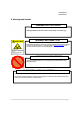
PSR78 Repeater User Manual V0.1 2. Warnings and Hazards WARNING! ELECTRIC SHOCK Opening the PSR78 could result in electric shock and may cause severe injury. WARNING! EXPOSURE TO RF Working with the repeater while in operation, may expose the technician to RF electromagnetic fields that exceed FCC rules for human exposure. Visit the FCC website at www.fcc.gov/oet/rfsafety to learn more about the effects of exposure to RF electromagnetic fields.
PSR78 Repeater User Manual V0.1 WARRANTY Opening or tampering the Axiom will void all warranties. Lithium Battery: CAUTION. RISK OF EXPLOSION IF BATTERY IS REPLACED BY INCORRECT TYPE. DISPOSE OF USED BATTERIES ACCORDING TO INSTRUCTIONS. Ethernet Instructions: This equipment is for indoor use only. All cabling should be limited to inside the building.
PSR78 Repeater User Manual V0.1 3. PSR78 Overview 3.1 Switches & Fault Indicators 3.1.1 LEDs The PSR78 has 3 LED’s located on inside of the repeater. Figure 1: Module LED PSR78 Power Soft Fail Hard Fail Solid Green OFF Solid Yellow OFF Solid Red OFF Specifications Module power is ON Module is powered OFF Soft Fail alarm exist in the system No Soft Fail alarm are present in the system Hard Fail alarm exist in the system No Hard Fail alarms are present in the system 3.1.
PSR78 Repeater User Manual V0.1 3.2 Switches and Ports 3.2.1 AC In Port The AC In Port is designed to work with the power cable that is included with the system. Figure 2: AC In Port 3.2.2 Battery Port The PSR78 can be connected to an ADRF-BBU (ADRF Battery Backup) to provide power during a power failure. If an ADRF-BBU is utilized, connect the ADRF-BBU to the PSR78 via the external battery port as shown in Figure 4.
PSR78 Repeater User Manual V0.1 3.2.3 Ethernet Port and Host/Remote Switch The Ethernet Port and Host/Remote switch are located underneath the waterproof cover. Loosen the handscrews and remove the cover to expose the Host/Remote switch and the Ethernet port to gain access to the system. Once the system is configured, it is recommended replace the cover and tighten the screws back into place.
PSR78 Repeater User Manual V0.1 3.5 Installation 3.5.1 Wall Mount Procedure The wall-mounting bracket has six mounting holes which are used to mount the bracket to the wall. The wall bracket must be securely attached to the wall in order to support the weight of the PSR78. After mounting the bracket to the wall, the PSR78 is placed on the mounting bracket using the four guard screws attached to the PSR78. The following steps should be followed while mounting the repeater: ① Take the PSR78 out of the box.
3.5.3 Grounding Install the ground cable which is included in the package on the side of the repeater as show in the figure below.
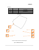
PSR78 Repeater User Manual V0.1 3.5.4 Antenna Separation/Isolation Separation between the antennas is necessary to prevent oscillation. Oscillation occurs when the signal entering the system continually reenters, due to the lack of separation between the donor and server antennas. In other words, the signal is being fed back into the system. This creates a constant amplification of the same signal. As a result, the noise level rises above the signal level.
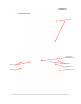
PSR78 Repeater User Manual V0.1 3.5.5 Line of Sight The donor antenna which points towards the base station typically has a narrow beam antenna pattern. As a result, a slight deviation away from the direction of the BTS can lead to less than optimum results. In addition, obstacles between the repeater and the BTS may impair the repeater from obtaining any BTS signal. As a result, the repeater cannot transmit signal to the coverage area.
PSR78 Repeater User Manual V0.1 4. PSR78 Web-GUI Setup The Web-GUI allows the user to communicate with the repeater either locally or remotely. To connect to the repeater locally, you will need a laptop with an Ethernet port and a RJ-45 crossover cable. To connect to the repeater remotely, you will need to have an active internet connection and the repeater must have either an internal modem or an Omnibox (ADRF Modem Box) connected to the repeater. 4.1 Repeater/PC Connection Using Web-GUI A.
PSR78 Repeater User Manual V0.1 4.2 Status Tab 4.2.1 Status- 700 MHz Status- 700 MHz 4.2.
PSR78 Repeater User Manual V0.1 4.2.3 Side Navigation Bar The side navigation bar located on the left hand side of the Web-GUI allows the user to switch between the two technolgies supported by the system. 4.2.4 SMR700 Band / SMR800 Band The band column displays the bandwidth that has been selected. The downlink column displays the center frequency of the selected band. The uplink column displays the center frequency of the selected band. 4.2.
PSR78 Repeater User Manual V0.1 4.2.7 AAI 4.2.8 Message Board Displays the recent system events for both the 700MHz and 800MHz sides. o o Clear: Clears the content that is currently being displayed on the Message Board Log File: Downloads the system Log File (events and alarms) to your computer 4.2.
PSR78 Repeater User Manual V0.1 4.2.
PSR78 Repeater User Manual V0.1 4.3.3 System o Reboot: Clicking the reboot button will have the following popup show up: Click OK to reboot the repeater or click Cancel to exit out o Factory Setting: Resets the repeater to the original factory settings 4.3.4 Oscillation Check Time This section allows the user to enable or disable the oscillation check feature and also specify the time interval at which the repeater checks for oscillation. 4.3.
PSR78 Repeater User Manual V0.1 4.3.6 Manual Gain Control o o o o o o o Downlink Gain: Allows the DL gain to be adjusted manually when AGC is OFF Uplink Gain: Allows the UL gain to be adjusted manually when AGC is OFF Downlink AGC Level: Allows the user to set the DL gain when AGC is enabled Uplink AGC Level: Allows the user to set the UL gain when AGC is enabled DL Output ALC Level: DL Output ALC Offset: DL /UL Gain Balance ON: 4.3.
PSR78 Repeater User Manual V0.1 4.4 Install Tab 4.4.
PSR78 Repeater User Manual V0.1 4.4.1.1 Bandwidth Selection This section allows the user to specify the desired bandwidths and frequencies ranges to be amplified. First select the desired bandwidth from the dropdown menu in the Bandwidth column. Next, input the center frequencies of the desired frequencies and click the Set button. Once the Set button is pressed, desired frequencies will be highlighted in the frequency table. 4.4.1.
PSR78 Repeater User Manual V0.1 4.4.1.5 Repeater Location Info / Repeater Installer Info This section allows the user to specify the address of the repeater and also the information of the installer. 4.4.1.5 Date & Time This section allows the user to specify the current date and time. 4.5 System The System tab allows the user to perform firmware updates, add/remove user accounts, and change the login credentials of the Administrator. 4.5.1 System: Account 4.5.1.
PSR78 Repeater User Manual V0.1 4.5.1.3 System: Administrator The Administrator section allows the Administrator to create additional Administrator accounts. Please note that the Administrator section is only available if you are logged into the system as the Administrator. 4.5.1.4 System: Change Password The Change Password section allows the current user who is logged into the system to change their login credentials.
PSR78 Repeater User Manual V0.1 4.5.2 System: User Log This section displays all the system activities that have taken place in the repeater along with the account associated with that event. 4.5.3 System: Update To perform a firmware update, click on the System tab and the following screen will show up.
PSR78 Repeater User Manual V0.1 4.6 Help If an internet connection is available, clicking on the Help Tab will redirect the user to our Technical Support page. 4.7 Logout Clicking the Logout button will log the current user off the system.
PSR78 Repeater User Manual V0.1 5. Maintenance Guide for PSR78 Repeater 5.1 Periodic Inspection Checklist a) b) c) Check for loose connections between the repeater and antennas. If connections are loose, make sure that all connections are tightly fastened properly. Cables and connectors are in good condition. Ensure that the repeater brackets are in good. condition and that the repeater is securely fastened 5.2 Preventive Measures for Optimal Operation 5.2.
PSR78 Repeater User Manual V0.1 6. Warranty and Repair Policy 6.1 General Warranty The PSR78 carries a Standard Warranty period of two (2) years unless indicated otherwise on the package or in the acknowledgment of the purchase order. 6.2 Limitations of Warranty Your exclusive remedy for any defective product is limited to the repair or replacement of the defective product. Advanced RF Technologies, Inc. may elect which remedy or combination of remedies to provide in its sole discretion.
PSR78 Repeater User Manual V0.1 7. Specifications 7.1 Electrical Specifications Parameters Frequency Specifications SMR700 UL 793 ~ 805MHz (BW: 12MHz) SMR700 DL 763 ~ 775 MHz (BW: 12MHz) SMR800 DL 851 ~ 869 MHz (BW: 18MHz) SMR800 UL 806 ~ 824 MHz (BW: 18MHz) Remark Port 2Donor, 2Server Composite Output Power +36 dBm 700 + 800 MHz Gain Ripple DL / UL ≤±1.5 dB p-p 700 + 800 MHz Maximum 90 dB Range 30 dB Step 0.
PSR78 Repeater User Manual V0.1 7.2 Mechanical Specifications Parameters Specifications Remark Dimension 17.9 X 22.5 X 12.3 inches Mount bracket excluded Weight < 92 lbs Mount bracket excluded Donor & Server Antenna Ports RF Ports N-type (F) Local Interface RJ45 (DHCP) Cooling 12V FAN 2EA IP Class NEMA 4 Outdoor Type Mounting Type Wall Mounting Color Red 7.
PSR78 Repeater User Manual V0.1 7.
PSR78 Repeater User Manual V0.
PSR78 Repeater User Manual V0.1 Appendix B: Shutdown Retry Logic The function of the built-in shutdown routine is to protect the repeater from any further damage from a hard-fail that the system may be experiencing. Within 5 seconds of a hard-fail alarm being detected, the repeater will start the shutdown routine. down by powering of the HPAs (high-powered amplifiers) for 30 seconds.