EPOCH-H (HP/HC) USER MANUAL Version 1.5 3116 Vanowen St. Burbank, CA 91505 USA Tel: 818-840-8131 Fax: 818-840-8138 www.adrftech.com Advanced RF Technologies, Inc.
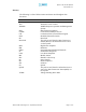
Epoch-H (HP/HC) RF Repeater User Manual V1.5 Glossary The following is a list of abbreviations and terms used throughout this document.
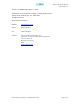
Epoch-H (HP/HC) RF Repeater User Manual V1.5 Version 1.5 (Modified December 7, 2009) Information in this document is subject to change without notice. Advanced RF Technologies, Inc. 1996-2009 All rights reserved. Please send comments to: E-Mail: info@adrftech.com Phone: (818) 840-8131 Fax: (818) 840-8138 Address: Advanced RF Technologies, Inc. Attention: Technical Publications Department 3116 Vanowen St. Burbank, CA 91505 USA www.adrftech.com Advanced RF Technologies, Inc.
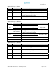
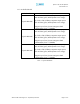
Epoch-H (HP/HC) RF Repeater User Manual V1.5 Revision History for Manual Version Author 1.0 G.T Kim 1.1 G.T Kim 1.2 1.3 G.T Kim K.Y Lee 1.4 1.5 K.Y Lee Sun Kim Revision History for Hardware Version Author Digital Part 1.0 RF Hardware Digital Part 2.0 RF Hardware Digital Part 3.0 RF Hardware 3.2 4.0 Digital Part RF Hardware Digital Part RF Hardware Revision History for Firmware Version Author 1.00 Software Team 1.12 1.13 2.01 2.04 3.00.15 3.00.16 4.00.36 Description First Generation.
Epoch-H (HP/HC) RF Repeater User Manual V1.5 Table of Contents 1. Introduction of Epoch-H ............................................................................. 7 1.1 Introduction ...................................................................................................... 7 1.1.1 Highlights ............................................................................................. 7 1.1.2 Available Models ..................................................................................
Epoch-H (HP/HC) RF Repeater User Manual V1.5 6.2 Limitations of Warranty .................................................................................... 47 6.3 Limitation of Damages ..................................................................................... 47 6.4 No Consequential Damages ............................................................................... 47 6.5 Additional Limitation on Warranty ...................................................................... 47 6.
Epoch-H (HP/HC) RF Repeater User Manual V1.5 1. Introduction of Epoch-H 1.1 Introduction Epoch-H series repeaters enhance outdoor wireless coverage in the most effective and cost efficient way. For its intelligent design and versatility, Epoch-H series repeaters are the ideal choice for wireless coverage problems outdoors. In many large scale in-building applications, Epoch-H series repeaters can also be used (e.g. malls, campuses, stadiums, etc.
Epoch-H (HP/HC) RF Repeater User Manual V1.5 1.1.2 Available Models Product ID Epoch-HP-05W Description Down Link: 5 W (37dBm) composite output power with 95 dB of gain (30 dB dynamic AGC range). Up Link: 0.5W (27dBm) composite output power with 95 dB of gain (30 dB dynamic AGC range). Supports up to Two (2) non-contiguous band combinations (5/10 + 5/15MHz) Down Link: 10 W (40dBm) composite output power with 95 dB of gain (30 dB dynamic AGC range). Epoch-HP-10W Up Link: 0.
Epoch-H (HP/HC) RF Repeater User Manual V1.5 Product ID Epoch-HC-05W Description Down Link: 5 W (37dBm) composite output power with 95 dB of gain (30 dB dynamic AGC range). Up Link: 0.5W (27dBm) composite output power with 95 dB of gain (30 dB dynamic AGC range). Supports either AF/BF, GUI Selectable Down Link: 10 W (40dBm) composite output power with 95 dB of gain (30 dB dynamic AGC range). Epoch-HC-10W Up Link: 0.5W (27dBm) composite output power with 95 dB of gain (30 dB dynamic AGC range).
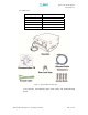
Epoch-H (HP/HC) RF Repeater User Manual V1.5 1.1.3 Parts List Quantity 1 1 1 1 Set 2 Sets 1 Description Repeater Ethernet Cable Ground Cable Anchor Bolts Keys Documentation CD* Table 3 – Parts List Figure 1 – Epoch-H Repeater Parts List * CD includes: User Manual, Quick Start Guide, and Troubleshooting Guide Advanced RF Technologies, Inc.
Epoch-H (HP/HC) RF Repeater User Manual V1.5 1.1.
Epoch-H (HP/HC) RF Repeater User Manual V1.5 Figure 4 – Epoch-H Inside Views Back Up Battery Switch (Page 16) LED Display (Page 15) Power Switch (Page 15) Figure 5 – Epoch-H Inner Door Views Figure 6 – Epoch-H Door Switch Advanced RF Technologies, Inc.
Epoch-H (HP/HC) RF Repeater User Manual V1.5 1.2 Warnings and Hazards WARNING! ELECTRIC SHOCK Opening the Epoch-H could result in electric shock and may cause severe injury. WARNING! EXPOSURE TO RF Working with the repeater while in operation, may expose the technician to RF electromagnetic fields that exceed FCC rules for human exposure. Visit the FCC website at www.fcc.gov/oet/rfsafety to learn more about the effects of exposure to RF electromagnetic fields.
Epoch-H (HP/HC) RF Repeater User Manual V1.5 WARRANTY Opening or tampering the Epoch-H will void all warranties. Lithium Battery: CAUTION. RISK OF EXPLOSION IF BATTERY IS REPLACED BY INCORRECT TYPE. DISPOSE OF USED BATTERIES ACCORDING TO INSTRUCTIONS. Ethernet Instructions : This equipment is for indoor use only. All cabling should be limited to inside the building.
Epoch-H (HP/HC) RF Repeater User Manual V1.5 2. Epoch-H Overview 2.1 Switches & Indicators 2.1.1 LEDs Epoch-H has three LEDs on the Inner Control Board panel of the repeater as shown below in Figure 7. Figure 7 – Epoch-H Repeater LED View POWER If the LED is lit GREEN, it indicates that there is AC power to the repeater. SOFT FAIL If the LED is lit YELLOW, it indicates that there is a soft fail alarm in the system. The detailed alarm information can be viewed via the local User GUI.
Epoch-H (HP/HC) RF Repeater User Manual V1.5 2.1.2 AC Power Switch Figure 8 – AC Power Switch The AC Power on/off switch is located on the inside of repeater (Figure 8). The switch should be powered on after the repeater has been installed properly. 2.1.3 Back Up Battery Switch & Battery Port Figure 9 – Battery Switch & Battery Port The Battery Switch can be used to provide power to the optional External Backup Battery (Figure 9).
Epoch-H (HP/HC) RF Repeater User Manual V1.5 2.1.4 Ethernet Port Figure 10 shows the Ethernet port is used to interface with the unit via RJ-45 crossover cable. Please set your network card to Obtain IP Address automatically and the repeater will assign an IP Address via DHCP. Figure 10 – Ethernet Port 2.1.5 Modem Module Figure 11 shows the Modem Module that is used to interface with the unit via modem. The modem will allow for remote configuration and monitoring via SNMP.
Epoch-H (HP/HC) RF Repeater User Manual V1.5 2.1.6 Other Ports - Donor Antenna Port Connect Donor Antenna. - Donor CPL Port You can check Donor output power. - Sever Antenna Port Connect Sever Antenna. - Server CPL Port You can check Donor output power. 2.2 Installation 2.2.1 Tools No special tools or equipments are needed to install the Epoch-H 2.2.2 Procedure Eight mounting holes are located on the wall-mounting bracket to attach it to the wall.
Epoch-H (HP/HC) RF Repeater User Manual V1.5 Figure 12 – Repeater Mounting Instructions Advanced RF Technologies, Inc.
Epoch-H (HP/HC) RF Repeater User Manual V1.5 2.2.3 Grounding A ground cable is included in the packaging and should be properly connected to the repeater as shown below. Figure 13 – Ground Cable Connection Advanced RF Technologies, Inc.
Epoch-H (HP/HC) RF Repeater User Manual V1.5 2.3 Antenna Separation/Isolation Separation between antennas is necessary to prevent oscillation. Oscillation occurs when the signal entering the system continually reenters, due to the lack of separation between the donor and server antennas. In other words, the signal is being fed back into the system. This creates a constant amplification of the same signal. As a result, the noise level rises above the signal level.
Epoch-H (HP/HC) RF Repeater User Manual V1.5 2.4 Line of Sight The donor antenna which points towards the base station typically has a narrow beam antenna pattern. As a result, a slight deviation away from the direction of the BTS can lead to less than optimum results. In addition, obstacles between the repeater and the BTS may impair the repeater from obtaining any BTS signal. As a result, the repeater cannot transmit signal to the coverage area.
Epoch-H (HP/HC) RF Repeater User Manual V1.5 3. Epoch-H AROMS Setup 3.1 Repeater/PC Connection Using AROMS i) Wait until the Power LED is lit in green. Connect the LAN cable between the laptop’s Ethernet port and the repeater’s Ethernet port. Note: Under Local Area Connection in Network Settings, make sure to select Obtain an IP address automatically under Internet Protocol (TCP/IP) properties.
Epoch-H (HP/HC) RF Repeater User Manual V1.5 iv) The following login screen will appear: If you are not the Super-User, please type in your assigned username & password which you should have received from the Super-User. The default username and password for the General User is adrf & adrf, respectively. If the username & password is typed in incorrectly, the following screen will appear: ** If you cannot connect to the Web GUI, please see the LAN Connectivity Troubleshooting Guide on Page 36.
3.2 Repeater Status 3.2.1 Epoch-HP If you click on Status tab, the following window will appear: In this window, the user can view the following: (To change any parameters, e.g., PCS Sub-Bands, Instantaneous Band Width, Gain Settings, AGC Level, etc., you must go to the Install or the Control window.) - CDMA Band: Will display the center frequencies of the 1900 MHz spectrums on the downlink and uplink respectively. Advanced RF Technologies, Inc.
Epoch-H (HP/HC) RF Repeater User Manual V1.5 - Power & Gain: Will display the repeater input, gain and output power on the downlink and uplink. 3.2.2 Epoch-HC If you click on Status tab, the following window will appear In this window, the user can view the following: (To change any parameters, e.g., Instantaneous Band Width, Gain Settings, AGC Level, etc., you must go to the Install or the Control window.) Advanced RF Technologies, Inc.
Epoch-H (HP/HC) RF Repeater User Manual V1.5 - Cellular Band: Will display the center frequencies of the 800 MHz spectrums on the downlink and uplink respectively. - Power & Gain: Will display the repeater input, gain and output power on the downlink and uplink. - Alarm: Will display seven alarms with three different status conditions (Normal, Soft Fail or Hard Fail). Door Open: Soft fail alarm Message Board: Will show up to recent 20 log messages (Alarms & Heartbeats).
Epoch-H (HP/HC) RF Repeater User Manual V1.5 3.
Epoch-H (HP/HC) RF Repeater User Manual V1.5 ⓑ Manual Gain Control - Downlink Gain Control (65 to 95 dB @ 0.5 dB step) - Uplink Gain Control (65 to 95 dB @ 0.5 dB step) - Downlink AGC Level Epoch-H-5W: 10 to 37 dBm @ 0.5 dB step, default value: 37 dBm Epoch-H-10W: 13 to 40 dBm @ 0.5 dB step, default value: 40 dBm Epoch-H-20W: 16 to 43 dBm @ 0.5 dB step, default value: 43 dBm - Uplink AGC Level Epoch-H-5 / 10 / 20W: 0 to 27 dBm @ 0.
Epoch-H (HP/HC) RF Repeater User Manual V1.5 ⓓ Heartbeat Time - Heartbeat on and off (Default mode is On) - Heartbeat periodic time (Range: 1 to 59 min @ 1 min step, default period is 20 min) Control Item Heartbeat ON/OFF Periodic Time Action Set Heartbeat Mode Set Heartbeat Time Setting Value ON/OFF 1 ~ 20 min @ 1 min step ⓔ Alarm Setting - RSSI Alarm at Donor (-100 ~ -50 dBm @ 0.
Epoch-H (HP/HC) RF Repeater User Manual V1.5 3.4 Repeater Install 3.4.1 Epoch-HP If you click on the Install tab, the following window will appear: ⓐ Band Selection Simply click on the desired operating bandwidth. The Epoch-HP has two independent RF paths: Path 1 and Path 2. Path 1 supports 5 MHz bandwidth or 10MHz bandwidth. Path 2 supports 5 or 15 MHz bandwidths.
Epoch-H (HP/HC) RF Repeater User Manual V1.5 (two contiguous or non-contiguous sub-bands: Path1and Path 2). Therefore, the instantaneous bandwidth that the Epoch-HP supports is 5, 10, 15, 20 or 25MHz. ⓑ SNMP Type in the assigned Site/Cascade ID and Manager IP Address. Default Site ID is ADRF. Default Manager IP address 100.10.10.100 ⓒ Repeater Location Please type in the physical address where the repeater is installed. Ex) Latitude: E/W (Upper Case) 034.123456 Longitude: N/S (Upper Case) 034.
Epoch-H (HP/HC) RF Repeater User Manual V1.5 If the Epoch-HP detects a problem during the installation process, it will show a prompt message, e.g., “Modem is not detected.” Please follow the instructions and address the problem to finish the installation process. If the problem persists, please contact our technical support. ⓕ Repeater Location Info Please type in the physical address where the repeater is installed.
Epoch-H (HP/HC) RF Repeater User Manual V1.5 3.4.2 Epoch-HC If you click on the Install tab, the following window will appear: ⓐ Band Selection Simply click on the desired operating bandwidth. The selected band will be highlighted in orange. To de-select, click again on the undesired band. The de-selected band will turn back white. Please see below Band Selection screen shot. Path 1 supports A”+A +A’ bandwidth; Path 2 supports B+B’ bandwidths; Band Selection Advanced RF Technologies, Inc.
Epoch-H (HP/HC) RF Repeater User Manual V1.5 ⓑ SNMP Type in the assigned Site/Cascade ID and Manager IP Address. Default Site ID is ADRF. Default Manager IP address is 100.10.10.100 ⓒ Location Please type in the physical address where the repeater is installed. Ex) Latitude: E/W (Upper Case) 034.123456 Longitude: N/S (Upper Case) 034.123456 ⓓ Repeater Static IP Will display the Repeater’s Static IP Address, Subnet Mask, and Gateway.
Epoch-H (HP/HC) RF Repeater User Manual V1.5 ⓔ Auto Installation Click the Install button to automatically setup the repeater. It may take up to 3 minutes to complete the process. You will see a gradual progress bar display. After the process is completed, a pop-up window will display “Installation Successfully Completed” message. Click on Status tab, the Installation box now changes from “Not Installed” to “Installed.
Epoch-H (HP/HC) RF Repeater User Manual V1.5 3.5 Repeater System If you click on the System tab, the following window will appear: Note: If you are the Super-User, you will see account management section under the System Window. If you are a general user, you will not be able to see the account management portion. Only the Super-User can add, delete and modify a user. The following window illustrates how a new user can be added by simply clicking on New Account.
Epoch-H (HP/HC) RF Repeater User Manual V1.5 Firmware Upgrade If you click on Firmware Upgrade, the following window will appear. You can browse through your PC and locate the firmware file. Once it’s selected, simply click on Update and it’ll upload the latest firmware automatically and close the session. You will need to re-login again. After the firmware update process in done, you will see the following pop-up window Advanced RF Technologies, Inc.
Epoch-H (HP/HC) RF Repeater User Manual V1.5 4. Maintenance Guide for Epoch-H 4.1 Periodic Inspection Checklist 4.1.1 Check for loose connections between the repeater and antennas. If connections are loose, make sure that all connections are tightly fastened properly. 4.1.2 Cables and connectors are in good condition. 4.1.3 Ensure that the repeater brackets are in good condition and that the repeater is securely fastened. 4.2 Preventive Measures for Optimal Operation 4.2.
5. Epoch-H Series Troubleshooting Guide 5.1 Connectivity Guide for LAN ∴ If you cannot connect to the Web GUI, please follow the steps listed below: i) If you see the icon below (Figure 16) Figure-16 - Check the Power Line to see whether or not the repeater is being powered correctly. - Use the Cross-over Cable that came with the repeater to connect the repeater to your laptop. If you still cannot connect, replace the cross-over cable with another one.
Epoch-H (HP/HC) RF Repeater User Manual V1.5 Instead of “Obtain an IP address automatically”, please select “Use the following IP address” and input the following values: IP address: 192.168.63.2 Subnet mask: 255.255.255.0 iii) If you see the icon in Figure 19, then the IP Address has been obtained. If you see this icon and still cannot connect to the unit, then please follow the steps listed below. Figure-19 Verify HOST/REMOTE switch is set to the HOST mode.
Epoch-H (HP/HC) RF Repeater User Manual V1.5 v) If the steps above do not remedy the situation and you still cannot connect to the Web GUI, then follow these steps: a. Verify that the switch is set to Host b.
5.2 Troubleshooting Guide for Repeater Alarm VSWR Status Parameter Hard Fail Soft Fail Troubleshooting 1. Make sure connectors are tight at each port. Sweep lines. 2. Use a 50 Ω dummy load, connect it to the Alarming Port to check whether the repeater is faulty. (e.g. if the Down Link is alarming, connect the dummy to the Server Port.) 3. If multiple Server Antennas are connected, connect only one antenna and recheck the Alarm.
Epoch-H (HP/HC) RF Repeater User Manual V1.5 (Default 6dB) 3. Go under ‘Control’ tab and turn off AGC and change gain manually to verify BDA is responding to changes. Recheck the measured values.
Epoch-H (HP/HC) RF Repeater User Manual V1.5 1. Go to ‘Control’ menu, click ‘Alarm Setting’ and verify ‘Heartbeat ON’ is checked and the appropriate time of 20 min. (the 20min mark can be lowered down to 1min in order to observe the alarm quicker) 2. Go to ‘Install’ menu and verify ‘Auto Connection’ under ‘Modem’ is checked. Then click ‘Disconnect’ and click ‘Connect’. Then No Heartbeats Internal Modem not sending out heartbeats. go to the ‘Status’ page to see if any modem activity has taken place.
Epoch-H (HP/HC) RF Repeater User Manual V1.5 1. Please verify under ‘Device Manager’ of Windows that the necessary drivers for the USB to serial adapter are installed. 2. Be sure to use the GUI software from the CD that came with the repeater. 3. If for some reason the CD is not available, contact 24HR tech support to acquire the appropriate one. 4. In the event of using a USB-to-serial converter, you must be sure to the ‘COM port’ Connectivity Issue Unable to Interface to repeater with GUI Software.
6. Warranty and Repair Policy 6.1 General Warranty The Epoch-H carries a Standard Warranty period of two (2) years unless indicated otherwise on the package or in the acknowledgment of the purchase order. 6.2 Limitations of Warranty Your exclusive remedy for any defective product is limited to the repair or replacement of the defective product. Advanced RF Technologies, Inc. may elect which remedy or combination of remedies to provide in its sole discretion. Advanced RF Technologies, Inc.
Epoch-H (HP/HC) RF Repeater User Manual V1.5 6.6 Return Material Authorization (RMA) No product may be returned directly to Advanced RF Technologies, Inc. without first getting an approval from Advanced RF Technologies, Inc. If it is determined that the product may be defective, you will be given an RMA number and instructions in how to return the product. An unauthorized return, i.e., one for which an RMA number has not been issued, will be returned to you at your expense.
Epoch-H (HP/HC) RF Repeater User Manual V1.5 Appendix A: Epoch-HP Specifications A.1 Electrical Specifications Parameters Frequency Range Specifications Downlink 1930~1995 MHz Uplink 1850~1915 MHz Frequency Error 0.05 ppm Band Selection 5/10 MHz + 5/15 MHz Gain Flatness Gain Composite Output Power (Down Link) Full band 1 dB Each band 2.5 dB Maximum 95 dB Step 0.
Epoch-H (HP/HC) RF Repeater User Manual V1.5 A.2 Mechanical Drawing Parameters Specifications Comments WxHxD Dimension Epoch-HP Series 17.89 x 19.76 x 111.45 Inches Weight Epoch-HP Series 83.8lbs Bracket excluded RF Ports N-Type (F) Donor & Server Antenna Ports Local Interface RJ45 (DHCP) External Convection/ Forced Air Cooling NEMA 4, IP55 Cooling NEMA Bracket excluded 12V FAN 2EA Outdoor Type A.
Epoch-H (HP/HC) RF Repeater User Manual V1.5 Appendix B: Epoch-HC Specifications B.1 Electrical Specifications Parameters Frequency Range Specifications Downlink 869~894MHz Uplink 824~849MHz Frequency Error 0.1ppm Band Selection AF/BF Remarks AF(A-869~880 MHz,A’-890~891.5MHz) Downlink BF(B-880~890 MHz,B’-892~894MHz) Band Reconfiguration GUI Selectable AF(A-824~835 MHz,A’-845~846.5MHz) Uplink BF(B-835~845 MHz,B’-847~849 MHz) Full band 1.5 dB Each band 1.
Epoch-H (HP/HC) RF Repeater User Manual V1.5 B.2 Mechanical Specifications Parameters Specifications Cabinet Wall Mounting Casing Class NEMA4 Minimum Weight 70.5 lbs Size 17.89 x 19.76 x 9.26 Inches Color PAKMEL PP#7414B Connector Type Input/output N Female Ethernet RJ45 Female Frame ground Brass Screw(M5x2) Cooling Remarks Outdoor Type External fan DC12V B.
Appendix C: Epoch-H Mechanical Drawing Advanced RF Technologies, Inc.
Appendix D: Epoch-HP Overview D.1 Black Diagram Advanced RF Technologies, Inc.
D.2 Components Epoch-HP 5W / 10W / 20W Epoch-HP Internal Components Power Supply It provides DC power to each module within the repeater. Controller It is responsible for monitoring the status of each module and controls the parameters. Also it interfaces with PC through Ethernet port. Down Converter Module The downlink RF signal that enters through the cavity filter is converted to IF frequency, which is later converted back to RF frequency through SAW filtering.
Epoch-H (HP/HC) RF Repeater User Manual V1.5 Duplexer It consists of two BPFs (band-pass filters): PCS TX (1930 ~ 1995 MHz) & RX (1850 ~ 1915 MHz) HPA It receives the output signal from the Up / Down converter module and amplifies the signal to the repeater’s rated maximum power level. Advanced RF Technologies, Inc.
Appendix E: Epoch-HC Overview E.1 Block Diagram Advanced RF Technologies, Inc.
E.2 Components Epoch-HC 5W / 10W / 20W Power Supply Control Board Up Link HPA Modem Coupler Up Link UDC Donor Port Duplexer Door Alarm On/Off Switch Down Link HPA Down Link UDC Modem Module Server Port DHCP Sub Board Advanced RF Technologies, Inc.
Epoch-H (HP/HC) RF Repeater User Manual V1.5 Power Supply It provides DC power to each module within the repeater. Control Board It is responsible for monitoring the status of each module and controls the parameters. Down Link UDC The downlink RF signal that enters through the cavity filter is converted to IF frequency, which is later converted back to RF frequency through SAW filtering.