Duo-i6515/6525/8030NM USER MANUAL Version 1.6 2607 Colorado Blvd. Los Angeles, CA 90041 USA Tel: 323-254-8131 Fax: 323-254-4928 www.adrftech.
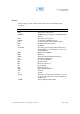
Duo-i6515/6525/8030NM User Manual V1.6 Glossary The following is a list of abbreviations and terms used throughout this document.
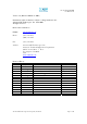
Duo-i6515/6525/8030NM User Manual V1.6 Version 1.6 (Released March 31, 2008) Information in this document is subject to change without notice. Advanced RF Technologies, Inc. 1996-2008. All rights reserved. Please send comments to: E-Mail: info@adrftech.com Phone: (323) 254-8131 (800) 313-9345 Fax: (323) 254-4928 Address: Advanced RF Technologies, Inc. Attention: Technical Publications Department 2607 Colorado Blvd., 1st Floor Los Angeles, CA 90041 USA www.adrftech.
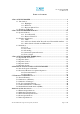
Duo-i6515/6525/8030NM User Manual V1.6 TABLE OF CONTENTS 1. DUO-I6515/6525/8030NM.............................................................................................. 6 1.1. Introduction...................................................................................................... 6 1.1.1. Highlights.......................................................................................... 6 1.1.2. Parts List ...................................................................................
Duo-i6515/6525/8030NM User Manual V1.6 APPENDIX B: MECHANICAL DRAWINGS.......................................................................... 35 APPENDIX C DUO-I6515/6525/8030NM OVERVIEW....................................................... 37 C.1 Block Diagram ............................................................................................... 37 C.2 Components....................................................................................................
Duo-i6515/6525/8030NM User Manual V1.6 1. Duo-i6515/6525/8030NM 1.1. Introduction The Duo-i6515/6525/8030NM is a dual band SMR (800 and 900 MHz) RF repeater which enhances in-building wireless coverage in the most effective and cost efficient way. For its intelligent design and versatility, the Duo-i6515/6525/ 8030NM is the ideal choice for wireless coverage problems indoors.
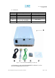
Duo-i6515/6525/8030NM User Manual V1.6 1.1.2. Parts List Label A B C D E F Qty 1 1 1 1 4 (for Duo-i6515/6525NM) or 6 (for Duo-i8030NM) 1 Description iDEN Repeater AC Power Cable Ethernet Cable (cross over) Ground Cable Anchor Bolts CD Table 1 – Parts List A B C D E F Figure 1 – Duo-i6515/6525/8030NM Repeater Parts List ** CD includes: (1) Duo-i6515/6525/8030NM User Manual & (2) Duoi6515/6525/8030NM Quick Start Guide Advanced RF Technologies, Inc.
Duo-i6515/6525/8030NM User Manual V1.6 1.1.3.
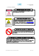
Duo-i6515/6525/8030NM User Manual V1.6 1.2. Warnings and Hazards WARNING! ELECTRIC SHOCK Opening the Duo- i6515/ 6525/ 8030NM could result in electric shock and m ay cause severe injury. WARNING! EXPOSURE TO RF Working with the repeater while in operation, may ex pose the technician t o RF electrom agnet ic fields that ex ceed FCC rules for human ex posure. Visit the FCC website at www.fcc.gov/ oet/ rfsafet y to learn more about the effect s of ex posure to RF electromagnetic fields.
Duo-i6515/6525/8030NM User Manual V1.6 WARRANTY Opening or t am pering the Duo- i6515/ 6525/ 8030NM will void all warrant ies. Lithium Battery : CAUTION. RISK OF EXPLOSION IF BATTERY IS REPLACED BY INCORRECT TYPE. DISPOSE OF USED BATTERIES ACCORDING TO INSTRUCTIONS. Ethernet Instructions : This equipment is for indoor use only. All cabling should be lim ited to inside the building.
Duo-i6515/6525/8030NM User Manual V1.6 2. Duo-i6515/6525/8030NM Overview 2.1 Operation Modes 2.1.1. Local Web GUI Host Mode This mode should be selected only if a Duo-i6515/6525/8030NM is used alone without being connected to any other device functioning as a host. Simply connect one end of the ethernet cable on the repeater monitor port and the other end on the PC’s LAN port.
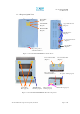
Duo-i6515/6525/8030NM User Manual V1.6 2.2 Switches & Indicators 2.2.1. LEDs The Duo-i6515/6525/8030NM has three LEDs on the front panel of the repeater as show below in Figure 4. Figure 4 – Duo-i6515/6525/8030NM Repeater LED View POWER If the LED is lit GREEN, it indicates that there is AC power to the repeater. SOFT FAIL If the LED is lit YELLOW, it indicates that there is a soft fail alarm in the system. The detailed alarm information can be viewed via the local web GUI.
Duo-i6515/6525/8030NM User Manual V1.6 2.2.2. AC Power Switch & DC Power Port for External Modem Box The AC Power on/off switch is located on the bottom of repeater (Figure 5). The switch should be powered on after the repeater has been installed properly. The DC Power Port can be used to provide power to the optional External Modem Box (Figure 5). Figure 5 – AC Power Switch & DC Power Port 2.2.3.
Duo-i6515/6525/8030NM User Manual V1.6 2.3 Installation 2.3.1 Tools No special tools or equipment are needed to install the Duoi6515/6525/8030NM. 2.3.2 Procedure Four (for Duo-i6515/6525NM) or six (for Duo-i8030NM) mounting holes are provided on the wall-mounting bracket to attach it to the wall. The wall bracket must be securely attached to sufficiently carry the weight of the Duoi6515/6525/8030NM, which is bolted to the wall bracket through four or six aligned mounting holes.
Duo-i6515/6525/8030NM User Manual V1.6 Figure 7 – Repeater Mounting Instructions Advanced RF Technologies, Inc.
Duo-i6515/6525/8030NM User Manual V1.6 2.3.3 Grounding A ground cable is included in the packaging and should be properly connected to the repeater as shown below. Figure 8 – Ground Cable Connection Advanced RF Technologies, Inc.
Duo-i6515/6525/8030NM User Manual V1.6 2.3.4 Antenna Separation/Isolation Separation between antennas is necessary to prevent oscillation. Oscillation occurs when the signal entering the system continually reenters, due to the lack of separation between the donor and server antennas. In other words, the signal is being fed back into the system. This creates a constant amplification of the same signal. As a result, the noise level rises above the signal level.
Duo-i6515/6525/8030NM User Manual V1.6 2.3.5 Line of Sight The donor antenna which points towards the base station typically has a narrow beam antenna pattern. As a result, a slight deviation away from the direction of the BTS can lead to less than optimum results. In addition, obstacles between the repeater and the BTS may impair the repeater from obtaining any BTS signal. As a result, the repeater cannot transmit signal to the coverage area.
Duo-i6515/6525/8030NM User Manual V1.6 3. Duo-i6515/6525/8030NM AROMS Setup 3.1 Repeater/PC Connection i) Wait until the Power LED is lit green. Connect the LAN cable between the laptop’s Ethernet port and the repeater’s Ethernet port. Note: Under Local Area Connection in Network Settings, make sure to select Obtain an IP address automatically under Internet Protocol (TCP/IP) properties. Advanced RF Technologies, Inc.
Duo-i6515/6525/8030NM User Manual V1.6 ii) Launch MS Internet Explorer (Version 6.0) Note: ADRF’s Web GUI has not been tested for compatibility with any other web browsers (e.g. Netscape, FireFox, Mozilla, etc.). iii) Type the following IP address into the address bar of MS Internet Explorer: http://192.168.63.1/home.asp iv) The following login screen will appear: If you are not the Super-User, please type in your assigned username & password which you should have received from the Super-User.
Duo-i6515/6525/8030NM User Manual V1.6 3.2 Repeater Status If you click on Status tab, the following window will appear: In this window, the user can view the following: (To change any parameters, e.g., iDEN Band, Gain Settings, you will need to go to the Install or Control window.) - iDEN Band: Will display the center frequencies of the 800 and 900 MHz spectrums on the downlink and uplink respectively. Advanced RF Technologies, Inc.
Duo-i6515/6525/8030NM User Manual V1.6 - Power & Gain: Will display the repeater input, gain and output power on the downlink and uplink. (Input is only displayed for Downlink) - Alarm: Will display five alarms with three different status conditions (Normal, Soft Fail or Hard Fail). Message Board: Will show up to recent 20 log messages (Alarms & Heartbeats). Installation: Will display repeater’s installation status (Not Installed or Installed).
Duo-i6515/6525/8030NM User Manual V1.6 3.3 Repeater Control If you click on the Control tab, the following window will appear: In this window, the user can adjust the following parameters: General Setting - Automatic Gain Control (Default mode is Off) - Downlink HPA on/off (Default mode is On) - Uplink HPA on/off (Default mode is On) - Uplink Tracking Mode on/off (Default mode is Off) Manual Gain Control - Downlink Gain Control Duo-i6515/6525NM: 40 to 65 dB @ 0.5 dB step Duo-i8030NM: 50 to 80 dB @ 0.
Duo-i6515/6525/8030NM User Manual V1.6 - Uplink AGC Level Duo-i6515NM: 5 to 15 dBm @ 0.5 dB step, default value: 15 dBm Duo-i6525NM: 15 to 25 dBm @ 0.5 dB step, default value: 25 dBm Duo-i8030NM: 20 to 30 dBm @ 0.5 dB step, default value: 30 dBm - Uplink Tracking Offset (0 to 10 dB @ 0.5 dB step, default value is 3 dB) System - If you click the Reboot button, the following message box will appear: When the system reboots, the latest settings will be saved.
Duo-i6515/6525/8030NM User Manual V1.6 3.4 Repeater Install If you click on the Install tab, the following window will appear: Band Selection Simply click on the desired operating bandwidth. SNMP Type in the assigned Site/Cascade ID and Manager IP Address. Default Site ID is ADRF. Default Manager IP address 100.10.10.100 Repeater Click the Install button to automatically setup the repeater. It may take up to 3 minutes to complete the process. You will see a gradual progress bar display.
Duo-i6515/6525/8030NM User Manual V1.6 Repeater Location Please type in the physical address where the repeater is installed. Repeater Installer Info Please type in the installer’s name, phone number and e-mail address for technical support. Repeater Static IP: Will display the Repeater’s Static IP Address, Subnet Mask, and Gateway. This information is necessary when using the Repeater in conjunction with the External Modem Box. Default values are: Repeater IP: 192.168.63.5 Subnet Mask: 255.255.255.
Duo-i6515/6525/8030NM User Manual V1.6 3.5 Repeater System If you click on System tab, the following window will appear: Note: If you are the Super-User, you will see an account management section under the System Window. If you are a general user, you will not be able to see the account management portion. Only the Super-User can add, delete and modify a user. The following window illustrates how a new user can be added by simply clicking on New Account.
Duo-i6515/6525/8030NM User Manual V1.6 Firmware Upgrade If you click on Firmware Upgrade, the following window will appear. You can browse through your PC and locate the firmware file. Once it is selected, simply click on Update and the latest firmware will be automatically uploaded and the session will close. You will need to re-login. After the firmware update process in done, you will see the following pop-up window. Advanced RF Technologies, Inc.
Duo-i6515/6525/8030NM User Manual V1.6 4. Maintenance Guide for Duo-i6515/6525/8030NM 4.1 Periodic Inspection Checklist 4.1.1 Check for loose connections to the repeater and antennas. If connections are loose, make sure that all connections are tightly fastened properly. 4.1.2 Check that cables and connectors are in good condition. 4.1.3 Ensure that the repeater brackets are in good condition and that the repeater is securely fastened. 4.2 Preventive Measures for Optimal Operation 4.2.
Duo-i6515/6525/8030NM User Manual V1.6 5. Warranty and Repair Policy 5.1 General Warranty The Duo-i6515/6525/8030NM carries a Standard Warranty period of five (5) years unless indicated otherwise on the package or in the acknowledgment of the purchase order. 5.2 Limitations of Warranty Your exclusive remedy for any defective product is limited to the repair or replacement of the defective product. Advanced RF Technologies, Inc.
Duo-i6515/6525/8030NM User Manual V1.6 5.6 Return Material Authorization (RMA) No product may be returned directly to Advanced RF Technologies, Inc. without first getting an approval from Advanced RF Technologies, Inc. If it is determined that the product may be defective, you will be given an RMA number and instructions in how to return the product. An unauthorized return, i.e., one for which an RMA number has not been issued, will be returned to you at your expense.
Duo-i6515/6525/8030NM User Manual V1.6 Appendix A: Specifications A.1 Electrical Specifications Parameters Specifications SMR900 DL 851 ~ 869 MHz or 862 ~ 869 MHz 806 ~ 824 MHz or 817 ~ 824 MHz 935 ~ 940 MHz SMR900 UL 896 ~ 901 MHz Duo-i6515NM +15 dBm SMR800 DL Frequency SMR800 UL Remark Composite Output Power (DL/UL) Duo-i6525NM +25 dBm Duo-i8030NM +30 dBm Gain Ripple DL / UL ≤ ±1.25 dB p-p Maximum 65 dB (80 dB for Duo-i8030NM) Range 25 dB (30 dB for Duo-i8030NM) Step 0.
Duo-i6515/6525/8030NM User Manual V1.6 A.2 Mechanical Specifications Parameters Dimension Weight Specifications Duo-i6515NM 14.13 x 18.88 x 6.42 inches Duo-i6525NM 14.13 x 18.88 x 6.42 inches Duo-i8030NM 13.95 x 19.5 x 7.
Duo-i6515/6525/8030NM User Manual V1.6 A.4 Power Specifications Parameters Specifications AC Power 100 ~ 130 AC AC Frequency 45 ~ 65 Hz AC Supply Protection Fuse DC Power Option -40 ~ -60 V / +20 ~ 30 V Power Consumption Duo-i6515NM ≤ 72 W Duo-i6525NM ≤ 140 W Duo-i8030NM ≤ 170 W Ground Comments External Threaded Stud A.5 Other Specifications Parameters Specifications MTBF > 100,000 Hours Certificates UL 60950, FCC Part 90 Warranty 5 Years Advanced RF Technologies, Inc.
Duo-i6515/6525/8030NM User Manual V1.6 Appendix B: Mechanical Drawings Duo-i6515/6525NM: Advanced RF Technologies, Inc.
Duo-i6515/6525/8030NM User Manual V1.6 Duo-i8030NM: Advanced RF Technologies, Inc.
Duo-i6515/6525/8030NM User Manual V1.6 Appendix C Duo-i6515/6525/8030NM Overview C.1 Block Diagram Duo-i6515/6525/8030NM Repeater Block Diagram Advanced RF Technologies, Inc.
Duo-i6515/6525/8030NM User Manual V1.6 C.2 Components Duo-i6515/6525NM: Noise Filter DHCP Sub Board Quad-Plexer Quad-Plexer Down Converter Up Converter Controller Interface Board Digital Filter Digital Filter Power Supply Duo-i6515/6525 Repeater Internal Components Diagram Advanced RF Technologies, Inc.
Duo-i6515/6525/8030NM User Manual V1.6 Duo-i8030NM Quad-plexer Quad-plexer Uplink HPA Downlink HPA Up Converter Power Supply for Modem Box Down Converter Controller Downlink Digital Filter Uplink Digital Filter Power Supply DHCP sub board Noise Filter Power port for Modem box Advanced RF Technologies, Inc.
Duo-i6515/6525/8030NM User Manual V1.6 Power Supply It provides DC power to each module within the repeater. Controller It is responsible for monitoring the status of each module and controls its parameters. Also it interfaces with PC through Ethernet port. Down Converter Module The downlink RF signal entered through the cavity filter is converted to IF frequency, which is later converted back to RF frequency again through digital filtering.