
User Manual

Delos200 RF Repeater
User Manual V1.1
Advanced RF Technologies, Inc. Proprietary Document Page 7 of 30
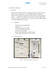
6. Donor Antenna Port
One end of the coax cable will connect to the “Donor Antenna Port” of
Delos200 while the other end of the cable will connect to the donor
antenna which is pointing towards the BTS.
The coax cable coming in from the donor antenna (pointing towards the
BTS)
7. USB Interface
For management and troubleshooting purposes, you can connect your PC
to Delos200 Manager via USB cable.
8. Power Switch
To turn the Delos200, you need to turn the power switch on.
9. AC/DC Power Port
To power the repeater, you need to connect the power supply to this port.
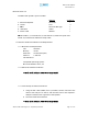
1.1.3 Available Models
Delos200 is available in all 1900 MHz PCS band combinations. The
following table illustrates the two standard models:
Product ID Description
Delos201
RF repeater with built-in sliding filters (5, 10
& 15 MHz ) @ 5 MHz increments across the
first 45 MHz PCS spectrum
(DL: 1930-1975 / UL: 1850-1895)
Delos202
RF repeater with built-in sliding filters (5, 10
& 15 MHz) @ 5 MHz increments across the
last 45 MHz PCS spectrum
(DL: 1945-1990 / UL: 1865-1910)
Table 1 – Delos200 Models