
User Manual

Delos200 RF Repeater
User Manual V1.1
Advanced RF Technologies, Inc. Proprietary Document Page 6 of 30
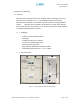
1. Server Antenna Port
One end of the coax cable will connect to the “Server Antenna Port” of
Delos200 while the other end of the cable will connect to the server
antenna which is pointing towards the intended coverage area.
2. VFD Display
In this display, you are able to view the repeater vitals in each link (e.g.
RSS, Gain, Output Power & Alarms).
** Please refer to Appendix B for more detailed information on how the
VFD button operates.
3. Power LED / Button
The Power LED will be lit Green if the power is turned on and will be not
lit if the power is turned off.
At the same time, by pressing the “Power LED” button, you can choose the
desired filer (5, 10 or 15 MHz).
** Please refer to Appendix B for more detailed information on how the
Power LED button operates.
4. VFD Button
By pressing the VFD button, you can see the repeater vitals on the VFD
display. The VFD display will be lit for 30 minutes and will then turn off.
It needs to be pressed again to display the repeater parameters on the
VFD display.
5. Alarm LED / Button
If there’s an alarm, the Alarm LED will be lit Red and will not be lit if there
isn’t any alarm.
At the same time, by pressing the “Alarm LED” button, you can choose the
desired operating band(s). By clicking on the “ALARM LED” button each
time, you will be sliding the filter (5, 10 or 15 MHz) to the right side of
the spectrum by an increment of 5 MHz bandwidth.
** Please refer to Appendix B for more detailed information on how the
Alarm LED button operates.