
User's Manual
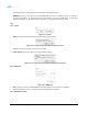
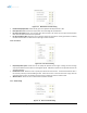
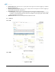
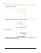
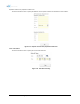
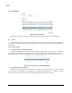
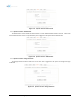
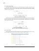
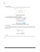
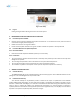
Table Of Contents
- 1. Introduction
- 2. Overview
- 3. Alarms
- 4. Installation
- 5. AXM2100-9543-ICS Web-GUI Setup
- 6. Maintenance Guide for AXM2100-9543-ICS Repeater
- 7. Warranty and Repair Policy
- 8. Specifications
- 9. mechanical drawing
- 10. Appendix

Figure 5-15 Manual Gain Control Setting
• Downlink Gain/Uplink Gain: Allows the UL gain to be adjusted manually when ALC is OFF
• DL Output ALC Level: Prevents the output power from exceeding the specified value
• DL Output ALC Offset: When the incoming signal level increases, the system will not adjust the attenuation
levels until the delta reaches the level specified
• DL /UL Gain Balance ON: Allows the user to enable or disable the gain balance. When gain balance is enabled,
the delta value between the downlink and uplink gains remain constant
5.3.6 ICS Control
Figure 5-16 ICS Control Setting
• DL/UL Adaptation Speed : Allows the user to specify the speed of the ICS engine. Setting this value too high
may impact EVM and could reduce the throughput speeds. Adaptation speeds can be adjusted based on the
selected bandwidth.
• Downlink ILC Level : Allows the user to specify the interference level control. The measured isolation value +
ILC Level will provide you with the MAX gain level. When the ILC Level + User Set Gain Level is larger than the
measured isolation value, ILC will adjust the gains levels to match the measure isolation value.
• Window Offset : Allows the user to shift the ICS cancellation window.
5.3.7 Alarm Setting
Figure 5-17 Alarm Threshold Setting
Advanced RF Technologies, Inc. 32