
User's Manual
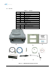
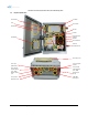
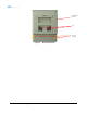
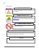
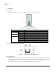

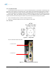
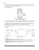
Table Of Contents
- 1. Introduction
- 2. Overview
- 3. Alarms
- 4. Installation
- 5. AXM2100-9543-ICS Web-GUI Setup
- 6. Maintenance Guide for AXM2100-9543-ICS Repeater
- 7. Warranty and Repair Policy
- 8. Specifications
- 9. mechanical drawing
- 10. Appendix

The AC Power on/off switch and AC selection switch are located at left of PSU. The AXM2100-9543-ICS PSU
can operate at 110V AC and 220V AC. The user should verify that the AC input voltage selection switch is set to the
correct voltage before powering on the AXM2100-9543-ICS.
2.2.4 Back Up Battery Port
Figure 2-5 Battery Backup Port
The AXM2100-9543-ICS can be connected to an ADRF-BBU (ADRF Battery Backup) to provide power during a
power failure. If an ADRF-BBU is utilized, connect the ADRF-BBU to the AXM2100-9543-ICS via the external battery
port.
(WARNING: The circuit switch on the ADRF-BBU must be set to OFF before connecting the ADRF-BBU to the
AXM2100-9543-ICS to prevent damage to the repeater or the ADRF-BBU and personal injury.)
Note: Please contact ADRF Technical Support for assistance if you are unfamiliar with the installation
procedure of our battery box.
2.3 RF Ports
Figure 2-6 RFU RF port
2.3.1 RF Ports
• DONOR – DIN female which is used to connect the donor antenna
• DONOR_CPL (30dB) – SMA female 30 dB coupling port which is used to monitor the amplified UL signal
• MODEM_ANT – SMA female port which is used to provide RF signal to the optional internal modem box
• SERVER_CPL (30dB) – SMA female 30 dB coupling port which is used to monitor the amplified DL signal
• SERVER – DIN female which is used to connect the server antenna
Advanced RF Technologies, Inc. 19