
User's Manual
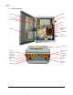
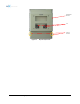
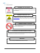
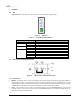
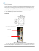
Table Of Contents
- 1. Introduction
- 2. Overview
- 3. Alarms
- 4. Installation
- 5. AXM1900-9543-ICS Web-GUI Setup
- 6. Maintenance Guide for AXM1900-9543-ICS Repeater
- 7. Warranty and Repair Policy
- 8. Specifications
- 9. mechanical drawing
- 10. Appendix

2.2.4 Back Up Battery Port
Figure 2-5 Battery Backup Port
The AXM1900-9543-ICS can be connected to an ADRF-BBU (ADRF Battery Backup) to provide power during a
power failure. If an ADRF-BBU is utilized, connect the ADRF-BBU to the AXM1900-9543-ICS via the external battery
port.
(WARNING: The circuit switch on the ADRF-BBU must be set to OFF before connecting the ADRF-BBU to the
AXM1900-9543-ICS to prevent damage to the repeater or the ADRF-BBU and personal injury.)
Note: Please contact ADRF Technical Support for assistance if you are unfamiliar with the installation
procedure of our battery box.
2.3 RF Ports
Figure 2-6 RFU RF port
2.3.1 RF Ports
• DONOR – DIN female which is used to connect the donor antenna
• DONOR_CPL (30dB) – SMA female 30 dB coupling port which is used to monitor the amplified UL signal
• MODEM_ANT – SMA female port which is used to provide RF signal to the optional internal modem box
• SERVER_CPL (30dB) – SMA female 30 dB coupling port which is used to monitor the amplified DL signal
• SERVER – DIN female which is used to connect the server antenna
Advanced RF Technologies, Inc. 18