
User's Manual
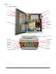
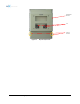
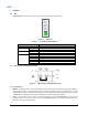
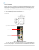
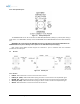
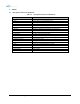
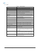
Table Of Contents
- 1. Introduction
- 2. Overview
- 3. Alarms
- 4. Installation
- 5. AXM1900-9543-ICS Web-GUI Setup
- 6. Maintenance Guide for AXM1900-9543-ICS Repeater
- 7. Warranty and Repair Policy
- 8. Specifications
- 9. mechanical drawing
- 10. Appendix

2. OVERVIEW
2.1 LED
AXM1900-9543-ICS has LEDs in the upper left corner as shown below in figure below.
POWER
SOFT FAIL
HARD FAIL
RSSI
Figure 2-1 LED panel
Table 2-1 RF Module LED Specifications
LED Indicator Specifications
Power
Solid Green
System power is ON
Soft Fail
Solid Yellow
Soft Fail alarm exist in the system
OFF
No Soft Fail alarm are present in the system
Hard Fail
Solid Red
Hard Fail alarm exist in the system
OFF
No Hard Fail alarms are present in the system
RSSI
Input < -85dBm
Zero (0) bar On
Input < -75dBm
One (1) bar On
Input < -65dBm
Two (2) bars On
Input < -55dBm
Three (3) bars On
Input < -45dBm
Four (4) bars On
Input >= -45dBm
Five (5) bars On
2.2 Ethernet Port and Host/Remote Switch
Figure 2-2 Ethernet Port and Host/Remote Switch
2.2.1 Ethernet Ports
• Modem – The Modem port is to only be used when the optional internal modem box (Digi Transport-WR21) is
used with the repeater. This port directly connects to the Ethernet port of the internal modem box. If a Digi
Transport WR-21 is being used with the repeater, used the included RJ-45 jumper cable to connect the Local
and Modem ports together and then flip the Host/Remote switch to the Remote position.
• Local – The Local port can be used to communicate directly with the AXM1900-9543-ICS using a RJ-45
crossover cable or can also be used to connect the AXM1900-9543-ICS to an external modem box or the
optional internal Digi Transport WR-21.
Advanced RF Technologies, Inc. 16