
User's Manual


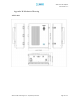


AEON-9030 RF Repeater
User Manual V1.0
Advanced RF Technologies, Inc. Proprietary Document Page 51 of 51
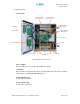
PCS Down Converter Module
The PCS downlink RF signal that enters through the cavity filter is converted to
IF frequency, which is later, converted back to RF frequency through digital
filtering.
PCS Up Converter Module
The PCS uplink RF signal that enters through the cavity filter is converted to IF
frequency, which is later, converted back to RF frequency through digital filtering.
Cellular Down Converter Module
The Cellular downlink RF signal that enters through the cavity filter is converted
to IF frequency, which is later, converted back to RF frequency through digital
filtering.
Cellular Up Converter Module
The PCS uplink RF signal that enters through the cavity filter is converted to IF
frequency, which is later, converted back to RF frequency through digital filtering.
Digital Filter
DSP (Digital Signal Processing) technology is utilized to achieve the highest level
of performance and filtering agility.
Duplexer
Consists of four BPFs (band-pass filters): PCS TX (1930 ~ 1990 MHz) & RX
(1850 ~ 1910 MHz), Cellular TX (869 ~ 894 MHz) & RX (824 ~ 849 MHz)
HPA
Receives the output signal from the PCS, Cellular Up / Down converter module
and amplifies the signal up to the repeater’s maximum rated power level.
LED Board
LED Board displays the state of the repeater. The detailed alarm information can
be viewed via the Web GUI.
PCS, Cellular Digital Filter
The Digital Filter is IF frequency converted back to RF frequency through digital
filtering.
Combiner
Combines Cellular and PCS signals. It consists of three BPFs (band-pass filters):
PCS and Cellular TX and RX.
Modem Module
Contains the CDMA 2000 modem (Kyocera M200).