AEON-9030 RF Repeater User Manual V1.0 AEON-9030 USER MANUAL Version 1.0 2607 Colorado Blvd. Los Angeles, CA 90041 USA Tel: 323-254-8131 Fax: 323-254-4928 www.adrftech.com Advanced RF Technologies, Inc.
AEON-9030 RF Repeater User Manual V1.0 Glossary The following is a list of abbreviations and terms used throughout this document.
AEON-9030 RF Repeater User Manual V1.0 Version 1.0 (July 1, 2009) Information in this document is subject to change without notice. Advanced RF Technologies, Inc. 1996-2009 All rights reserved. Please send comments to: E-Mail: info@adrftech.com Phone: (323) 254-8131 Fax: (323) 254-4928 Address: Advanced RF Technologies, Inc. Attention: Technical Publications Department 2607 Colorado Blvd., 1st floor Los Angeles, CA 90041 USA www.adrftech.com Advanced RF Technologies, Inc.
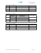
AEON-9030 RF Repeater User Manual V1.0 Revision History for Manual Version Author 1.0 K.Y.LEE Description First Generation. Date July 1, 2009 Revision History for Hardware Version Author Digital Part 1.0 RF Hardware Description First Generation. First Generation. Date Revision History for Firmware Version Author 1.0 Anthony Jang Description First Generation Advanced RF Technologies, Inc.
AEON-9030 RF Repeater User Manual V1.0 Table of Contents 1. Introduction of AEON-9030 ................................................................................... 7 1.1 Introduction ....................................................................................................... 7 1.1.1 Highlights.............................................................................................. 7 1.1.2 Parts List .....................................................................................
AEON-9030 RF Repeater User Manual V1.0 A.5 Other Specifications ....................................................................................... 47 Appendix B: Mechanical Drawing ................................................................................... 48 Appendix C: AEON-9030 Overview ................................................................................ 49 C.1 Black Diagram................................................................................................ 49 C.
AEON-9030 RF Repeater User Manual V1.0 1. Introduction of AEON-9030 1.1 Introduction AEON-9030 repeaters enhance indoor wireless coverage in the most effective and cost efficient way. Intelligent design and versatility make AEON-9030 repeaters the ideal choice for indoor wireless coverage problems. DSP (Digital Signal Processing) technology is utilized to achieve the highest level of performance and filtering agility. 1.1.
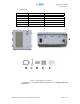
AEON-9030 RF Repeater User Manual V1.0 1.1.2 Parts List Label A B C D E F Qty 1 1 1 1 Kit (Set of 4) 1 Kit (Set of 4) 1 Description AEON-9030 Repeater Ethernet Cable (crossover) Ground Cable 3/8” Nuts & Bolts 1/2” Nuts & Bolts CD** Table 1: Parts List A B C D E F Figure 1: AEON-9030 Repeater Parts List ** CD includes: (1) AEON-9030 User Manual & (2) AEON-9030 Quick Start Guide Advanced RF Technologies, Inc.
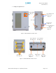
AEON-9030 RF Repeater User Manual V1.0 1.1.3 Repeater Quick View Display LED (Page 13) Upper Guard Screw Bracket Screw (Page 18) Door Lock Bracket Screw (Page 18) Lower Guard Screw (Page 18) Ground Hole (Page 19) Figure 2: AEON-9030 Front & Side Views Donor Antenna Port (Page 16) Anchor Bolt Hole (Page 18) AC Power Supply Cord (Page 15) Server Antenna Port (Page 16) Ethernet Port (Page 15) Back Up Battery Port (Page 15) Figure 3: AEON-9030 Back & Bottom Views Advanced RF Technologies, Inc.
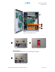
AEON-9030 RF Repeater User Manual V1.0 Figure 4: AEON-9030 Inside View Figure 5: AC Power Switch - Figure 6: 110/200V Select Switch Selector switch See installation instructions before connecting to the supply Figure 7: Battery Select Switch Advanced RF Technologies, Inc.
AEON-9030 RF Repeater User Manual V1.0 1.2 Warnings and Hazards WARNING! ELECTRIC SHOCK Opening the AEON-9030 could result in electric shock and may cause severe injury. WARNING! EXPOSURE TO RF Working with the repeater while in operation, may expose the technician to RF electromagnetic fields that exceed FCC rules for human exposure. Visit the FCC website at www.fcc.gov/oet/rfsafety to learn more about the effects of exposure to RF electromagnetic fields.
AEON-9030 RF Repeater User Manual V1.0 WARRANTY Opening or tampering the AEON-9030 will void all warranties. Lithium Battery: CAUTION. REPLACEMENT OF BATTERY WITH THE INCORRECT TYPE MAY LEAD TO A RISK OF EXPLOSION. DISPOSE OF USED BATTERIES ACCORDING TO INSTRUCTIONS. Ethernet Instructions: This equipment is for indoor use only. All cabling should be limited to inside the building.
AEON-9030 RF Repeater User Manual V1.0 2. AEON-9030 Overview 2.1 Switches & Indicators 2.1.1 LEDs The AEON-9030 has ten LEDs on the front panel of the repeater as shown below in Figure 8.
AEON-9030 RF Repeater User Manual V1.
AEON-9030 RF Repeater User Manual V1.0 2.1.2 AC Power Switch Figure 9: AC Power Switch The AC Power on/off switch is located on the inside and bottom of repeater (Figure 9). The switch should be powered on after the repeater has been installed properly. 2.1.3 Back Up Battery Switch & Battery Port Figure 10: Battery Switch & Battery Port The Battery Switch can be used to provide power to the optional External Backup Battery.
AEON-9030 RF Repeater User Manual V1.0 2.1.4 Ethernet Port Figure 11 shows the Ethernet port which is used to interface with the unit via RJ-45 crossover cable. Verify that the Host/Remote switch is set to Host and set your network adapter to “Obtain an IP Address Automatically” and the repeater will assign an IP Address via DHCP. The Host/Remote switch should only be set to Remote when an external modem box is being used to monitor the unit. Figure 11: Ethernet Port 2.1.
AEON-9030 RF Repeater User Manual V1.0 2.2 Installation 2.2.1 Tools No special tools or equipments are needed to install the AEON-9030. 2.2.2 Procedure The wall-mounting bracket has six mounting holes which are used to mount the bracket to the wall. The wall bracket must be securely attached to the wall in order to support the weight of the AEON-9030. After mounting the bracket to the wall, the AEON-9030 is placed on the mounting bracket using the four guard screws attached to the AEON-9030.
AEON-9030 RF Repeater User Manual V1.0 Figure 13: Repeater Mounting Instructions Advanced RF Technologies, Inc.
AEON-9030 RF Repeater User Manual V1.0 2.2.3 Grounding A ground cable is included in the packaging and should be properly connected to the repeater as shown below. Figure 14: Ground Cable Connection Advanced RF Technologies, Inc.
AEON-9030 RF Repeater User Manual V1.0 2.3 Antenna Separation/Isolation Separation between antennas is necessary to prevent oscillation. Oscillation occurs when the signal entering the system continually reenters, due to the lack of separation between the donor and server antenna. This creates a constant amplification of the same signal. As a result, the noise level rises above the signal level.
AEON-9030 RF Repeater User Manual V1.0 2.4 Line of Sight The donor antenna which points toward the base station typically has a narrow beam antenna pattern. As a result, a slight deviation away from the direction of the BTS can lead to less than optimum results. In addition, obstacles between the repeater and the BTS may impair the repeater from obtaining any BTS signal. As a result, the repeater cannot transmit signal to the coverage area.
AEON-9030 RF Repeater User Manual V1.0 3. AEON-9030 AROMS Setup 3.1 Repeater/PC Connection Using AROMS i) Wait until the Power LED is lit in green. Connect the LAN cable between the laptop’s Ethernet port and the repeater’s Ethernet port. Note: Under Local Area Connection in Network Settings, make sure to select Obtain an IP address automatically under Internet Protocol (TCP/IP) properties.
AEON-9030 RF Repeater User Manual V1.0 If you are not the Super-User, please type in your assigned username & password which you should have received from the Super-User. The default username and password for the General User is adrf & adrf, respectively. If the username & password is typed in incorrectly, the following screen will appear: ** If you cannot connect to the Web GUI, Please see the LAN Connectivity Troubleshooting Guide on Page 38 or visit http://www.adrftech.com/wiki/index.
AEON-9030 RF Repeater User Manual V1.0 3.2 Repeater Status PCS Repeater Status If you click on Status tab, the following window will appear: Cellular Repeater Status Advanced RF Technologies, Inc.
AEON-9030 RF Repeater User Manual V1.0 In this window, the user can view the following: (To change any parameters, e.g., Channel frequency, bandwidth, Gain Settings, AGC Level, etc., you must go to the Install or the Control window.) - CDMA Band: Will display the center frequencies of the 1900 MHz filtered BWs on the downlink and uplink respectively. - Cellular Band: Will display the center frequencies of the 800 MHz filtered BWs on the downlink and uplink respectively.
AEON-9030 RF Repeater User Manual V1.0 - Clear: Will delete message board contents. - Log File: Will download repeater’s log file. - Alarm History: Will provide additional alarm log for repeater’s status. - Installed icon: Shows the current “Install” status (Installed or Not Installed). - Modem icon: Shows the current modem status (Disabled, Connected, Not connected). - Power icon: Shows the current electric source [AC power, Battery (Shown when an external battery box is installed)].
AEON-9030 RF Repeater User Manual V1.0 - Alarms: The unit will display seven alarms with three different status conditions (Normal, Soft Fail or Hard Fail). Message Board: Displays the 20 most recent log messages (Alarms & Heartbeats). Installation: Displays the repeater’s installation status (Not Installed or Installed). Repeater Info: Displays the repeater’s serial number, and location information (latitude and longitude coordinates).
AEON-9030 RF Repeater User Manual V1.0 3.3 Repeater Control If you click on Control tab, the following window will appear: In this window, the user can adjust the following parameters: ⓐ General Setting - Automatic Gain Control (Default mode is Off) - Downlink HPA on/off (Default mode is Off) - Uplink HPA on/off (Default mode is Off) Advanced RF Technologies, Inc.
AEON-9030 RF Repeater User Manual V1.0 AGC Mode AGC (Auto Gain Control) adjusts the variable gain of the repeater on both downlink and uplink to ensure a constant specified output power. The functionality of the AGC feature is assured under the condition that the input BTS signal is within the specified AGC range and that sufficient isolation exists between antennas. By default, the AGC ON box is not checked. To change the AGC levels on the Uplink and Downlink, AGC ON must be checked.
AEON-9030 RF Repeater User Manual V1.0 - If you click the Factory Setting button, the following message box will appear: Factory Setting will erase the saved settings by the user and change all the parameters to the factory default settings. ⓓ Heartbeat Time - Heartbeat is disabled. ⓔ Alarm Setting - Downlink Signal Low (-90 ~ -30 dBm @ 0.5 dB step, default value: -80 dBm) - Downlink Signal Not Detected (-90 ~ -96 dBm @ 0.5 dB step, default value: -90 dBm) - Downlink RF Power (2 ~ 10 dB @ 0.
AEON-9030 RF Repeater User Manual V1.0 3.4 Repeater Install If you click on the Install tab, the following window will appear: PCS Install Cellular Install Advanced RF Technologies, Inc.
AEON-9030 RF Repeater User Manual V1.0 ⓐ PCS Band Selection - Step 1: Channel Select - Step 2: Bandwidth Select - Step 3: FA Select * 3 Separate Channel Selections are possible. The AEON-9030 has three independent RF PCS channels: Channel 1, Channel 2 and Channel 3. Each channel supports 1.25 MHz to 18.75MHz bandwidth. One can use any of the three channels (three contiguous: Unit will not filter 1FA as guard band nor non-contiguous channels).
AEON-9030 RF Repeater User Manual V1.0 Please type in the coordinates where the repeater is installed. Ex) Latitude: N/S (Upper Case) 034.123456 Longitude: E/W (Upper Case) 034.123456 ⓓ Modem Box Settings: Will display the Repeater’s Static IP Address, Subnet Mask, and Gateway. This information is necessary when using the Repeater in conjunction with an External Modem Box. Default values are: Repeater IP: 192.168.63.5 Subnet Mask: 255.255.255.0 Gateway: 192.168.63.
AEON-9030 RF Repeater User Manual V1.0 Please type in the physical address where the repeater is installed. ⓖ Repeater Installer Info Please type in the installer’s: company, name, phone number and e-mail address for technical support. ⓗ Date and Time: Sets the date and time for the internal clock (required for Log Messages) Advanced RF Technologies, Inc.
AEON-9030 RF Repeater User Manual V1.0 3.5 Repeater System If you click on the Account menu under the System tab, the following window will appear: Note: If you are the Super-User, you will see account management section under the System Window. If you are a general user, you will not be able to see the account management portion. Only the Super-User can add, delete and modify a user. The following window illustrates how a new user can be added by simply clicking on New Account.
AEON-9030 RF Repeater User Manual V1.0 User Log If you click on the User Log menu under the System tab, the following window will appear. The following window displays the changes made to the Repeater settings. Firmware Update If you click on Firmware Upgrade, the following window will appear. You can browse through your PC and locate the firmware file. Once it’s selected, click on Update and it will upload the firmware automatically and close the session.
AEON-9030 RF Repeater User Manual V1.0 4. Maintenance Guide for AEON-9030 4.1 Periodic Inspection Checklist 4.1.1 Check for loose connections to the repeater and antennas. If connections are loose, make sure that all connections are tightly fastened. 4.1.2 Check that cables and connectors are in good condition. 4.1.3 Ensure that the repeater brackets are in good condition and that the repeater is securely fastened. 4.2 Preventive Measures for Optimal Operation 4.2.
AEON-9030 RF Repeater User Manual V1.0 5. AEON-9030 Troubleshooting Guide 5.1 Connectivity Guide for LAN If you are unable to connect to the Web GUI, please follow the steps listed below: i) If you see the icon below (Figure 17) Figure 17 - Check the Power Line to see whether or not the repeater is being powered correctly. - Use the Cross-over Cable that came with the repeater to connect the repeater to your laptop. If you still cannot connect, replace the cross-over cable with another one.
AEON-9030 RF Repeater User Manual V1.0 iii) If you see the icon in Figure 20, then the IP Address has been obtained. If you see this icon and still cannot connect to the unit, then please follow the steps listed below. Figure 20 Verify HOST/REMOTE switch is set to the HOST mode. - When the unit is set to Host Mode, the IP address for the unit is 192.168.63.1 - When the unit is set to Remote Mode, the IP address for the unit is 192.168.63.
AEON-9030 RF Repeater User Manual V1.0 iv) Use Microsoft Internet Explorer to log into the Web-GUI Note: ADRF’s Web GUI is not compatible with other web browsers such as Netscape, Mozilla’s Firefox, Opera, etc. Please type the following IP address into the address bar of MS Internet Explorer: http://192.168.63.1/home.asp or http://192.168.63.
AEON-9030 RF Repeater User Manual V1.0 5.2 Troubleshooting Guide for Repeater Alarm VSWR Status Parameter Hard Fail Soft Fail Troubleshooting 1. Make sure connectors are tight at each port. Sweep lines. 2. Use a 50 Ω dummy load, connect it to the Alarming Port to check whether the repeater is faulty. (e.g. if the Down Link is alarming, connect the dummy to the Server Port.) 3. If multiple Server Antennas are connected, connect only one antenna and recheck the Alarm.
AEON-9030 RF Repeater User Manual V1.0 (Default 6dB) 3. Go under ‘Control’ tab and turn off AGC and change gain manually to verify BDA is responding to changes. Recheck the measured values.
AEON-9030 RF Repeater User Manual V1.0 1. Please verify under ‘Device Manager’ of Windows that the necessary drivers for the USB to serial adapter are installed. 2. Be sure to use the GUI software from the CD that came with the repeater. 3. If for some reason the CD is not available, contact 24HR tech support to acquire the appropriate one. 4. In the event of using a USB-to-serial converter, you must be sure to the ‘COM port’ Connectivity Issue Unable to Interface to repeater with GUI Software.
AEON-9030 RF Repeater User Manual V1.0 6. Warranty and Repair Policy 6.1 General Warranty The AEON-9030 carries a Standard Warranty period of three (3) years unless indicated otherwise on the package or in the acknowledgment of the purchase order. 6.2 Limitations of Warranty Your exclusive remedy for any defective product is limited to the repair or replacement of the defective product. Advanced RF Technologies, Inc. may elect which remedy or combination of remedies to provide in its sole discretion.
AEON-9030 RF Repeater User Manual V1.0 Appendix A: Specifications A.1 Electrical Specifications Parameters Specification Down Link 869 - 894MHz Up Link 824 - 849MHz Comments Cellular *Frequency Bands Down Link 1930MHz ~ 1990MHz Up Link 1850MHz ~ 1910MHz PCS Down Link (Max) 30dBm / 3FA Up Link (Max) 30dBm / 3FA Max RF output power Cellular Sub Bands A”+A+B+A’+B’, A”+A, A+A’, B+B’, A, B, A+A”+ A’ Selectable blocks of 10, 12.
AEON-9030 RF Repeater User Manual V1.0 (*1) Cellular Sub Bands 1 BAND Selection 2 BAND Selection 1 25MHz FULL (869~894MHz) Full band 2 869~880MHz A”+A 3 870~880MHz A 4 880~890MHz B 1 869~880MHz, 890~891.5MHz A”+A, A’ 2 870~880MHz, 890~891.5MHz A, A’ 3 880~890MHz, 891.5~894MHz B, B’ A.2 Mechanical Drawing Parameters Specifications Comments Dimension 22” X 17.9.” X 9.65” Inches WxHxD Bracket excluded Weight 80.
AEON-9030 RF Repeater User Manual V1.0 Over voltage category Over voltage category II Pollution degree Pollution degree 2 A.5 Other Specifications Parameters Specifications MTBF > 100,000 Hours Certificates UL 60950, FCC Part 15, 24 Warranty 3 Years Advanced RF Technologies, Inc.
AEON-9030 RF Repeater User Manual V1.0 Appendix B: Mechanical Drawing AEON-9030 Advanced RF Technologies, Inc.
AEON-9030 RF Repeater User Manual V1.0 Appendix C: AEON-9030 Overview C.1 Black Diagram Advanced RF Technologies, Inc.
AEON-9030 RF Repeater User Manual V1.0 C.2 Components AEON-9030 Cellular FWD/RVS UP/Down Converter PCS FWD/RVS UP/Down Converter PCS FWD/RVS HPA, Duplexer LED Board Cellular FWD/RVS HPA, Duplexer PCS Digital Filter Control Board Cellular Digital Filter Combiner Modem Coupler Donor Port Server Port Ethernet Port Power Supply AEON-9030 Internal Components Power Supply Provides DC power to each module within the repeater.
AEON-9030 RF Repeater User Manual V1.0 PCS Down Converter Module The PCS downlink RF signal that enters through the cavity filter is converted to IF frequency, which is later, converted back to RF frequency through digital filtering. PCS Up Converter Module The PCS uplink RF signal that enters through the cavity filter is converted to IF frequency, which is later, converted back to RF frequency through digital filtering.