
User's Manual

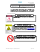
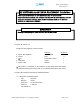
Table Of Contents
- Introduction of Epoch-M1P
- Overview
- Warnings and Hazards
- Epoch-M1P Parts List
- Epoch-M1P Software Installation and Requirements
- 1.4.1 Minimum PCS Requirements
- 1.4.2 Epoch-M1P Software Installation
- ** Refer to the Software Setup Guide
- ** Refer to the USB Setup Guide
- Pre-Installation using Epoch-M1P Software
- Step by Step Instructions for Installation
- User Manual V1.0 using Epoch-M1P Software
- Menu Structure
- Using the Epoch-M1P Software
- Alarms
- Default Control Settings
- Maintenance Guide for Epoch-M1P
- Periodic Inspection Checklist
- Preventive Measures for Optimal Operation
- Troubleshooting
- Tx & Rx LEDs
- Common Installation Problems
- Warranty and Repair Policy
- General Warranty
- Limitations of Warranty

Epoch-M1P RF Repeater
User Manual V1.0
1. Server Antenna Port
One end of the coax cable will connect to the “Server Antenna Port” of
Epoch-M1P while the other end of the cable will connect to the server
antenna which is pointing towards the intended coverage area.
2. Power LED / Button
The Power LED will be lit Green if the power is turned on and will be not
lit if the power is turned off.
3. Wireless Modem Access
You can manually place or take off the wireless modem by taking of the
four screws.
4. Donor Antenna Port
One end of the coax cable will connect to the “Donor Antenna Port” of
Epoch-M1P while the other end of the cable will connect to the donor
antenna which is pointing towards the BTS.
The coax cable coming in from the donor antenna (pointing towards the
BTS)
5. VFD Display
In this display, you are able to view the repeater vitals in each link (e.g.
RSS, Gain, Output Power & Alarms).
6. Alarm LED / Button
If there’s an alarm, the Alarm LED will be lit Red and will not be lit if there
isn’t any alarm.
At the same time, by pressing the “Alarm LED” button, you can choose the
desired operating band(s). By clicking on the “ALARM LED” button each
time, you will be sliding the filter (5, 10 or 15 MHz - depending on the
Epoch-M1P model) to the right side of the spectrum by an increment of
25 channel steps (1.25 MHz bandwidth).
**
t
Please refer to Appendix B for more detailed information on how the
Alarm LED but ons operates.
Advanced RF Technologies, Inc. Proprietary Document Page 6 of 38