
User's Manual
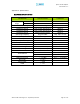
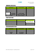
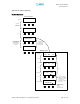
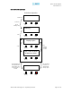
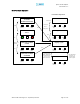
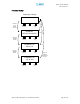
Table Of Contents
- Introduction of Epoch-M1P
- Overview
- Warnings and Hazards
- Epoch-M1P Parts List
- Epoch-M1P Software Installation and Requirements
- 1.4.1 Minimum PCS Requirements
- 1.4.2 Epoch-M1P Software Installation
- ** Refer to the Software Setup Guide
- ** Refer to the USB Setup Guide
- Pre-Installation using Epoch-M1P Software
- Step by Step Instructions for Installation
- User Manual V1.0 using Epoch-M1P Software
- Menu Structure
- Using the Epoch-M1P Software
- Alarms
- Default Control Settings
- Maintenance Guide for Epoch-M1P
- Periodic Inspection Checklist
- Preventive Measures for Optimal Operation
- Troubleshooting
- Tx & Rx LEDs
- Common Installation Problems
- Warranty and Repair Policy
- General Warranty
- Limitations of Warranty

Epoch-M1P RF Repeater
User Manual V1.0
Appendix B: Button Operation
Normal Operation
Power Off
Initializing....
POWER VFD ALARM
Normal Operation
6 sec
16 sec
Booting Time
Power On
(off) (off)
POWER VFD ALARM
(Green) (Red)
If the VFD button
is clicked, the
display will be
come up again.
The VFD display will
be disappeared 30
minutes later since
the VFD button is
touched.
Display Cycle*
POWER VFD ALARM
(Green) (off)
POWER VFD ALARM
(Green) (off)
DL: IN GAIN OUT
-102 80.0 -10
If there is no modem
hardware, the display
will be blank. If modem
is there, but not
connected, the display
will be ‘ DIS’ .
UL: IN GAIN OUT
-102 77.0 -10
Downlink
Uplink
4 sec
BW CH. MODEM
15M 150 CON
4 sec
STATUS
INSTALLED
Band & Channel
Install Status
4 sec
If repeater is not
installed, message
will be
STATUS
NOT INSTALLED
POWER VFD ALARM
(Green) (off)
POWER VFD ALARM
(Green) (off)
POWER VFD ALARM
(Green) (off)
POWER VFD ALARM
(Green) (off)
4 sec
Display Cycle
Advanced RF Technologies, Inc. Proprietary Document Page 35 of 38