
User's Manual
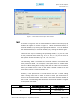
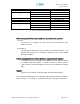
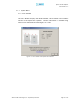
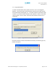
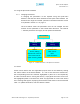
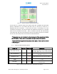
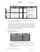
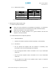
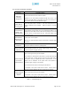
Table Of Contents
- Introduction of Epoch-M1P
- Overview
- Warnings and Hazards
- Epoch-M1P Parts List
- Epoch-M1P Software Installation and Requirements
- 1.4.1 Minimum PCS Requirements
- 1.4.2 Epoch-M1P Software Installation
- ** Refer to the Software Setup Guide
- ** Refer to the USB Setup Guide
- Pre-Installation using Epoch-M1P Software
- Step by Step Instructions for Installation
- User Manual V1.0 using Epoch-M1P Software
- Menu Structure
- Using the Epoch-M1P Software
- Alarms
- Default Control Settings
- Maintenance Guide for Epoch-M1P
- Periodic Inspection Checklist
- Preventive Measures for Optimal Operation
- Troubleshooting
- Tx & Rx LEDs
- Common Installation Problems
- Warranty and Repair Policy
- General Warranty
- Limitations of Warranty

Epoch-M1P RF Repeater
User Manual V1.0
4.2 Common Installation Problems
Problem Possible Solution
USB port is
not being
recognized
You would need to install the driver for the USB cable which can be
found with the CD that comes with the repeater.
Regardless if you have already installed the USB driver once, if are
connecting the USB cable to a new USB port on the PC for the very first
time, you will need to install the USB driver again.
The power
green LED on
the front panel
is not lit.
Check if the power switch is turned on. Also verify if the power cord is
securely connected to the repeater. Make sure there’s no power
outage.
GUI Software &
Laptop - No
Communication
The very first time during installation, once you connect the USB cable
to the repeater and the laptop, the PC will automatically detect a new
hardware has been added in the system and will prompt you to install
the driver which can be found in the CD. The driver needs to be
installed only once.
Status Window –
Weak Signal or
Donor RSS
Check that the donor and server antennas are connected to the proper
antenna ports on the repeater.
Reposition or rotate the donor antenna around until a stronger signal
is received.
Low Isolation or
Oscillation
Increase the separation between the donor and server antennas by
moving the antennas around or by rotating them.
Downlink/Uplink
VSWR Alarm
Check the cabling because RF signals maybe leaking and also verify
that the connectors are tightly secured.
Downlink/Uplink
Input Power
Overload Alarm
Add an attenuator after the donor/server antenna to reduce the strong
donor/server signal coming into the repeater.
If the repeater is connected to a DAS, there’s a good chance the DAS
system could cause a strong signal to come in on the uplink side of
the repeater, causing an
Uplink Input Power Overload
alarm. If this
happens, add an attenuator on the uplink side of the repeater or
control the signal coming in from the DAS.
Try to reduce the AGC Power Level using the GUI software.
An oscillation in the system could cause this alarm. Check if there is
sufficient separation between the donor and the server antennas.
Downlink/Uplink
Over Power
Alarm
Add an attenuator after the donor/server antenna to reduce the strong
donor/server signal coming into the repeater.
An oscillation in the system could cause this alarm. Check if there is
sufficient separation between the donor and the server antennas.
Table 12 – Troubleshootin
g
Ti
p
s
Advanced RF Technologies, Inc. Proprietary Document Page 30 of 38