
User's Manual
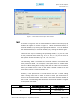
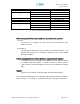
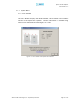
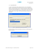
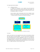
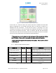
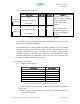
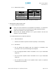
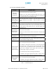
Table Of Contents
- Introduction of Epoch-M1P
- Overview
- Warnings and Hazards
- Epoch-M1P Parts List
- Epoch-M1P Software Installation and Requirements
- 1.4.1 Minimum PCS Requirements
- 1.4.2 Epoch-M1P Software Installation
- ** Refer to the Software Setup Guide
- ** Refer to the USB Setup Guide
- Pre-Installation using Epoch-M1P Software
- Step by Step Instructions for Installation
- User Manual V1.0 using Epoch-M1P Software
- Menu Structure
- Using the Epoch-M1P Software
- Alarms
- Default Control Settings
- Maintenance Guide for Epoch-M1P
- Periodic Inspection Checklist
- Preventive Measures for Optimal Operation
- Troubleshooting
- Tx & Rx LEDs
- Common Installation Problems
- Warranty and Repair Policy
- General Warranty
- Limitations of Warranty

Epoch-M1P RF Repeater
User Manual V1.0
2.2 Using the Epoch-M1P Software
2.2.1 Changing Parameters
In changing the parameters of the repeater using the Epoch-M1P
Software, note that the values entered into the Epoch-M1P Software are
limited to the ranges and modes specified in the Menu Structure section
as explained in Section 2.1 on page 15.
The chart below shows the parameters that can be changed and the
location of each parameter in the Control Menu Structure. The asterisk
“*” denotes parameters that apply to both uplink and downlink.
Control Menu
General Alarm
Setting Setting
Reboot Periodic Time
Factory Setting Date & Time
Manual Gain Control* RSSI*
Input Overload
*
AGC Level Control*
Uplink Tracking Offset
Figure 12 - Variable Parameters in the Epoch-M1P Software
2.3 Alarms
All the various alarms that are supported by Epoch-M1P can be viewed by clicking
the “Alarm” button on the Status Window. If a soft or hard fail alarm should occur,
the corresponding alarm box would be highlighted in yellow or in red respectively.
In order to find out what is causing the alarm(s), simply place the mouse cursor over
the highlighted yellow or red alarm box
(Note: only applicable to some of the alarms)
and a message will appear, displaying the threshold value and the current measured
value. To update the window, click the “Refresh” button.
Advanced RF Technologies, Inc. Proprietary Document Page 25 of 38