
User's Manual
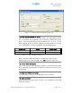
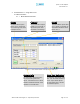
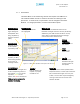
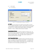
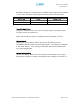
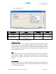
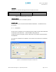
Table Of Contents
- Installation Guide for Epoch-S02
- Environmental requirements
- Warnings and Hazards
- Tools and Recommendations for Installation
- Epoch-S02 Parts List
- Step by Step Instructions for Installation
- User Manual V1.1 using OMS V4.01
- Menu Structure
- Using the Epoch-S02 OMS V4.01
- Alarms
- Default Control Settings
- Maintenance Guide for Epoch-S02 OMS V4.01
- Periodic Inspection Checklist
- Preventive Measures for Optimal Operation
- Troubleshooting
- Epoch-S02 OMS V4.01 Scenarios
- Heartbeat Scenarios
- Warranty and Repair Policy
- General Warranty
- Specific Product Warranty Instructions
- A.1 Minimum Requirements
- A.2 Epoch-S02 OMS V4.01 Installation/Startup
- Appendix B: Specifications

Epoch-S02 RF Repeater
User Manual V1.1
2.1.3.2 Alarm Setting
Figure 2.1.3.2 Alarm Setting Window of the Epoch-S02 OMS V4.01
Control Item Action Downlink Uplink
RF Power Sets Alarm Level 3 ~ 40 dB --
RSSI Sets Low RSSI Alarm Level -120 ~ -30 dBm -120 ~ -30 dBm
Input Overload
Sets Donor Input
Overload Level
-90 ~ -20 dBm -90 ~ -20 dBm
Table 2.1.3.2 Alarm Threshold Values
Downlink RF Power
The RF Power Alarm is the pilot power difference between the reference pilot
power measured from the embedded modem when the repeater is installed
initially and the current pilot power measured value from the embedded modem
when the repeater is operating (HPA ON). If the difference exceeds the RF Power
value, the alarm will turn on.
RSSI
The RSSI Alarm value is the minimum RSSI value that the Epoch-S02 requires to
ensure optimal coverage. The RSSI Alarm value will turn on when the RSSI is
lower than the threshold value (refer to the RSSI value in the Alarm Setting
window).
Input Overload
An Input Overload Alarm occurs when the input signal strength to the Epoch-S02
exceeds the threshold value (refer to the Uplink/Downlink Input OverIoad values
in the Alarm Setting window).
Advanced RF Technologies, Inc. Proprietary Document Page 18 of 31