
User's Manual

Flex 4ES/EX Instruction Manual
September 2016
Page 17 of 37
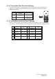
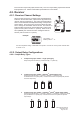
4.1.7.3. Toggled Pushbutton with LED Indication – Inline Top/Bottom
Pushbutton Configuration
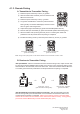
Set pushbutton toggled function (latching output relay) with
LED indications. LED 1 ~ 4 shown inside the shaded box
illustrates which LED on the transmitter lights up when the
designated pushbutton is pressed. Refer to section 4.2.4
JP4/JP5 inline jumper settings.
* PB1…PB4 Pushbutton number.
* Normal Normal momentary contact.
* LED 1 ~ LED 4 Pushbutton toggled function with designated LED indication.
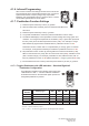
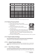
4.1.7.4. A/B Pushbutton Select with LED Indication – Inline Top/Bottom
Pushbutton Configuration
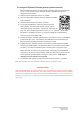
There are 4 different types of A/B selector sequence available. Choose one that is
most suitable for your application. Refer to section 4.2.4 JP4/JP5 inline jumper
settings and section 5.1 output relay connections.
Type-A selector sequence : A B
Type-B selector sequence : Off A B
Type-C selector sequence : A B A+B
Type-D selector sequence : Off A B A+B
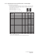
Function
Number
Display Type PB1 PB2 PB3 PB4
101
1 orange + 1 Red Normal Normal A/1&2 Normal
102
1 orange + 2 Reds Normal Normal B/1&2 Normal
103
1 orange + 3 Reds Normal Normal C/1&2 Normal
104
1 orange + 4 Reds Normal Normal D/1&2 Normal
33
3 Greens + 3 Reds Normal Normal Normal A/3&4
34
3 Greens + 4 Reds Normal Normal Normal B/3&4
35
3 Greens + 5 Reds Normal Normal Normal C/3&4
36
3 Greens + 6 Reds Normal Normal Normal D/3&4
105
1 orange + 5 Reds Normal Normal A/1&2 A/3&4
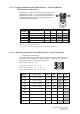
Function
Number
Display Type PB1 PB2 PB3 PB4
1
1 Red Normal Normal Normal LED 4
17
1 Green + 7 Reds Normal Normal LED 3 LED 4
18
1 Green + 8 Reds Normal LED 2 LED 3 LED 4
19
1 Green + 9 Reds LED 1 LED 2 LED 3 LED 4