
User's Manual


Flex 6ES/EX Instruction Manual
September 2016
Page 28 of 37
5. Receiver Installation
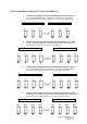
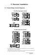
5.1. Output Relay Contact Diagrams
Flex 6ES (single speed model)
Flex 6EX (dual speed model)
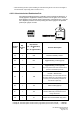
* For 9~36VDC power supply, wire #1 corresponds to the negative charge (-) and wire #3 corresponds
to the positive charge (+), wire #2 is GROUND.
* If PB5 (or PB6) is set to A/B pushbutton select function, connect output A to K9 (or K10) and output B to
K11 (or K12). Refer to section 4.1.8.2 on how to set to this function.