
Product Info

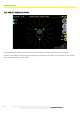
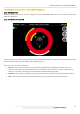
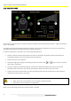


FILTER MODULE
72
The technical materials and information contained in this document are strictly confidential and the exclusive property of Advanced Microwave Engineering s.r.l.
These materials and information are intended solely for the purpose designated and may not be used otherwise.
It is not permitted to disclose or reproduce them in whole or in part without express written permission.
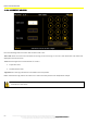
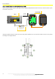
14.2 CONNECTIONS AND HW CONFIGURATIONS
The connection requires only one UTP cable, Cat. 5E or higher (LAN) between the device and one of the free 'Sensor' ports
in the CPU of the system.
The device address selector must be set to the same position (address) as one of the anti-collision sensors in the system
according to the diagram below.
A
B
C
D
E
F
GHJ H
K
L
M
N
P R
S T
U
V
W
X
Y
Z
a
b
c
EXT PWR
ANT LF
LED1-6
16
JP1
ADR_TX
- +
SW2
SW1
BUS2
CPU
FILTER SENS
ADDRESS
SELECTOR
UTP CONNECTION
CABLE, CAT. 5E