
Installation Manual

INSTALLATION ON THE VEHICLE
19
The technical materials and information contained in this document are strictly confidential and the exclusive property of Advanced Microwave Engineering s.r.l.
These materials and information are intended solely for the purpose designated and may not be used otherwise.
It is not permitted to disclose or reproduce them in whole or in part without express written permission.
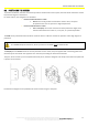
8.3 CONNECTIONS
8.3.1 General instructions
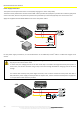
The necessary connections on the systems can be summarised in two categories:
Data Connections
Power Supply Connections
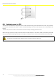
Data Connections
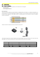
The data connection between the system devices is established with a UTP cable. As a minimum requirement, it is
recommended to use a UTP cable belonging to category 5E or higher. In the case of RJ45 connections, the same sequence
of colours must be followed on each cable end, and it is recommended to use the sequence of colours according to
Standard TIA/EIA-568-B.
The data connection is between Hub-CPU and between Sensors-Hub.
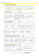
The maximum length of the connection depends on the supply voltage of the system and on the cross section of the UTP
cable (AWG). For convenience purposes, the reference tables of both connections are provided.
CPU
-
HUB Connection
HUB
-
SENSOR Connection
VDC
AWG 26
AWG 24
VDC
AWG 26
AWG 24
12 V
20m
40m
12 V
3m
6m
24 V
50m
100m
24 V
25m
50m