
Installation Manual


TURNING-ON AND CONFIGURATION
38
The technical materials and information contained in this document are strictly confidential and the exclusive property of Advanced Microwave Engineering s.r.l.
These materials and information are intended solely for the purpose designated and may not be used otherwise.
It is not permitted to disclose or reproduce them in whole or in part without express written permission.
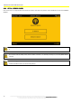
If some sensors have not been identified, try repeating the search operation. If it still fails, check:
Position of all selectors (they must be set to 0)
Connections between sensor and HUB.
If no sensor is identified, check:
Connections between HUB and CPU
HUB power supply.
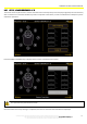
Make sure that each ID matches those that had been previously noted down, and then associate to each ID a position
identified with a number from 1 to 8.
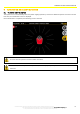
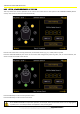
The sensors must be positioned in the following way compared to the driver’s cabin:
FRONT SENSORS: 2 - 1 - 8
REAR SENSORS: 4 - 5 - 6
LATERAL SENSORS: 3 - 7
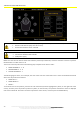
The following figures show, as an example, the case of the 3 sensors of the basic kit for a front counterbalanced vehicle
which must be positioned as follows:
FRONT LEFT: 2
FRONT RIGHT: 8
REAR: 5
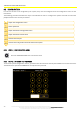
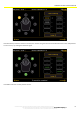
To associate an ID to the position, press the ID to be associated (it will be highlighted in yellow, on the right side of the
screen), and then press the position (it will turn yellow, on the left side). The position associated to the ID is displayed
next to the selected ID. Proceed in the same way with the other sensors, and then press the ASSIGN ID key.