
Installation Manual

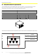
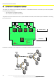

INSTALLATION ON THE VEHICLE
29
The technical materials and information contained in this document are strictly confidential and the exclusive property of Advanced Microwave Engineering s.r.l.
These materials and information are intended solely for the purpose designated and may not be used otherwise.
It is not permitted to disclose or reproduce them in whole or in part without express written permission.
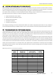
8.6 STOPPING DISTANCES AND ACTIVATION DISTANCES
When installing a safety supporting system to be used for reducing the risk of man-vehicle and vehicle-vehicle collisions,
it is necessary to take into account which activation distances have to be considered for the system operation. The purpose
of this is to adjust the system so that a truly helpful signal can be given to the pedestrian worker.
As a matter of fact, the distance at which a pedestrian worker wearing a Tag or a vehicle has to be detected in order to
give effective aid for the prevention of collisions depends on many factors such as:
Shape and dimension of the vehicle.
Reaction time of the detection system
Reaction time of the driver
Deceleration distance
Conditions of the ground
Even though formulating an accurate mathematical model of the vehicle stop physical phenomenon is very complex, it
can be schematised following a simplified model in order to draw attention to the main physical phenomena involved.
8.7 Vehicle deceleration and driver's response distances
The space/distance a vehicle needs to stop safely must be clearly assessed. Firstly, evaluate the deceleration distance- the
distance the forklift truck needs to reach zero speed starting from a given speed from the instant the braking system is
actuated. In turn, this space depends on the speed of the forklift truck, the maximum deceleration set in the parameters
of the vehicle, and the response time of the systems of the forklift truck.
Deceleration, as well as maximum speed, can be set to different values depending on the type of load, vehicle and ground.
The maximum distances for industrial vehicles are standardised by ISO 6292 that sets the maximum stopping distances
from the instant when the braking system is actuated. Such values will be taken as reference. The driver's reaction distance
is to be added to the acceleration distance afterwards. Such distance is associated to the time between the alert and the
driver's action stop the vehicle. As a normal practice, this response time is estimated in 1 second. By way of an example,
find below two charts with the values referring to deceleration space and total stopping space for two types of vehicles
defined in the standard.
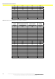
Chart 1 Stopping distances as per ISO 6292 A1 (<16000 kg)
Speed
[km/h]
Deceleration
distance [m]
(ISO6292 A1)
Driver reaction
distance @1s [m]
Total
braking
time [m]
3 0.8 0.8 1.6
4 1.3 1.1 2.4
5 1.8 1.4 3.2
6 2.2 1.7 3.8
7 2.5 1.9 4.5
8 2.9 2.2 5.1
9 3.3 2.5 5.8
10 3.6 2.8 6.4
11 4.0 3.1 7.0
12 4.4 3.3 7.7
13 4.7 3.6 8.3
14 5.2 3.9 9.1
15 5.8 4.2 10.0