
Installation Manual
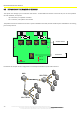

INSTALLATION ON THE VEHICLE
27
The technical materials and information contained in this document are strictly confidential and the exclusive property of Advanced Microwave Engineering s.r.l.
These materials and information are intended solely for the purpose designated and may not be used otherwise.
It is not permitted to disclose or reproduce them in whole or in part without express written permission.
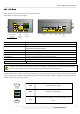
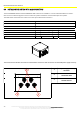
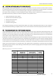
FEMALE (FRONT VIEW)
PIN
Colour Function
1 Brown VDC
2 Blue VDC
3 White GND
4 Green GND
5 Pink Normally Open Relay 1
6 Yellow Common Relay 1
7 Black Normally Closed Relay 1
8 Grey Normally Open Relay 2
9 Red Common Relay 2
10 Violet Normally Closed Relay 2
11 Grey-Pink Not Used
12 Red-Blue Not Used
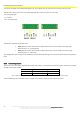
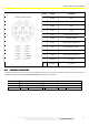
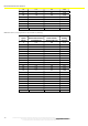
8.4.1 LENGTH OF CONNECTIONS
The cables supplied are 5-m long, and they are AWG 24. If longer connections are to be made between HUB and sensors
and between HUB and CPU, M12 AMF CABLES (5M) may be used as extensions.
CPU
-
HUB Connection
HUB
-
SENSOR Connection
VDC
AWG 26
AWG 24
VD
C
AWG 26
AWG 24
12 V
20m
40m
12 V
3m
6m
24 V
50m
100m
24 V
25m
50m